Source:
Experimental Television Center, Binghamton, NY (1976)RASTER
Raster refers to the scanned cathode ray tube (CRT); it appears as a rectangular block of light. The picture tube of a television receiver or monitor is a CRT and the display of an oscilloscope is also a CRT. The raster is produced by the electron beam inside the tube moving horizontally and slightly downward to create 525 blank lines when there is no video input. The horizontal and vertical motion is called scanning.
SCANNING PROCESS
The following description refers to the standard 625 line system used in the many cuntry. The process is similar for most video equipment but the numbers indicated may be different for different machines and in different countries.
Video is a series of still information which is displayed so rapidly that, due to persistence of vision, the eye and brain perceive motion.
The scanning process produces a raster by drawing 625 horizontal lines across and down the screen. The drawing is done by a beam of electrons. The beam first scans each of the 312 1/2 odd lines across and slightly down the screen (one field) and then returns to the top and scans each of the 312 1/2 even lines between the odd lines (one field) to compose one Frame of 625 lines or the raster.
The beam begins to scan at the top left on the first odd line and moves horizontally and slightly downward to the right edge. This one line is called a trace. The beam then returns from the right to the left at the next odd line to begin a new trace. The return portion of the beam is not seen because it is blanked out by a blanking pulse. The return portion of the beam is called the retrace. The scanning of each of the 312 1/2 odd lines continues in this manner to the bottom of the rectangle. It takes 1/54th of one second to complete the scanning of all the odd lines, when the beam reaches the bottom of the screen it must return to the top to begin the scanning process for all the even lines. The return of the beam from the bottom to the top is also blanked out so it is not seen. The 312 1/2 odd lines which are scanned make up one field.
When the beam has returned to the top, scanning of the even lines begins. The process is the same as the one for odd lines except that only even lines are scanned. The alternation of odd and even lines is called, interlaced scanning. For each horizontal line the beam moves across from left to right and slightly down then back to the left side again (the retrace) to begin the next even line. At the bottom the beam again returns to the top while the screen is blanked out and the beam is ready to scan odd lines. The 312 1/2 even lines which are scanned also make up one field and take 1/54th of one second.
The odd field and the even field together comprise one frame of 625 horizontal lines. There are 25 frames displayed every second (frame frequency) or 50 fields displayed every second (field frequency). In each second there are a total of 15,620 lines: 1 frame=625 lines, 25 frames per second - 25 x 625 = 15,620 lines per second. This is called line frequency.
The scanning process occurs in both the camera and the monitor and must be regulated so that the process happens at exactly the same time and at the same rate for both. This timing is accomplished by sync pulses (see below).
odd field
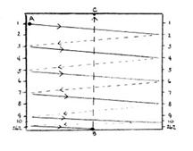
trace begins at A
trace moves A to 2 left to right
retrace moves 2 to 3 right to left
when trace reaches B, beam moves from B to C and is blanked out
solid lines are traces
broken lines are retraces
even field
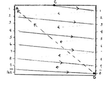
trace begins at C
retrace moves C to 1 left to right
retrace moves 1 to 2 right to left
when trace reaches D, beam moves back to A (blanked out)
one frame consists of 1 odd and 1 even field

solid lines are odd traces
broken lines are even traces
retraces are not shown
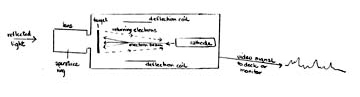
MONITOR
Monitor: video signal goes directly into this to display the image
Receiver: video signal must be converted to RF (radio frequency) before it can be displayed. A cable from RF output of the camera or deck is attached to the antenna leads of a television set (receiver).
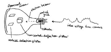
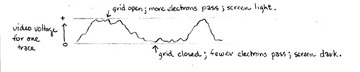
The cathode produces a beam of electrons which are emitted in the direction of the fluorescent screen. The control grid has a tiny hole which opens and allows more electrons to pass through, or closes and lets fewer electrons pass. A positive voltage opens the grid and a negative voltage closes the grid. A negative voltage is kept on the grid, but this is variable by the brightness control on the monitor or receiver. By turning the brightness up, you reduce the negative voltage, open the control grid and allow more electrons to pass brightening the screen. By turning the brightness down, the negative voltage is increased, the control grid is closed and fewer electrons pass, darkening the screen. By varying the brightness you change the average background illumination. If the brightness is very high when the video signal is fed in, even the peak video voltages may not darken the screen; if brightness is down, the peak video voltages may not open the grid enough to allow my electrons to pass and the screen does not get lighter.
The scanning process is the same as previously described. The motion of scanning is controlled by the horizontal and vertical deflection plates. The electron beam is moved from left to right by the horizontal deflection plates to produce the traces. The beam is moved slightly downward as it scans horizontally and back to the top from the bottom by the vertical deflection plates.
The screen is coated with a fluorescent material which releases light when hit by electrons; the more electrons which hit the material, the more light is released. The video signal sent from the camera is composed of fluctuations in voltage. A positive voltage produced by the camera by the presence of light will open the control grid and allow more electrons to pass, brightening the screen. A negative voltage produced by the camera in the absence of light will close the control grid, allowing fewer electrons to pass and. darkening the screen.
The contrast control on a monitor increases the difference between the positive and negative peaks of a video signal. Since the positive peak lightens the screen and a negative peak darkens the screen, an increased difference between the two will cause an increase in the difference between light and dark.
Thus in one trace there can be many variations of relative light and dark. 525 traces, each with its variations, compose a mosaic of lights and darks which can be perceived as an image
CAMERA
Light is reflected by an object and enters the camera through the aperture opening of the lens. Light falls on the camera tube (usually a vidicon tube). The target is that section of the tube sensitive to light (photosensitive). The light causes electrons to be emitted producing areas of positive charge; the more light, the more electrons emitted and the greater the number of positively charged areas.
The cathode emits a beam of electrons in the direction of the target. This beam sweeps the target from left to right horizontally and slightly down in the same manner as the monitor scans and at the same rate. The deflection coils move the deflection beam horizontally across the target and vertically from top to bottom and back up during the entire scanning process. As the beam scans the target the areas of negative charge produced by light hitting these areas attract the negatively charged electrons while those areas of negatively charged electrons while those areas of negative charge produced by less light do not attract the electrons. Thus the number of returning electrons varies with the number of positive charges on the target. If th target has many areas of positive charge (indicating the presence of light), fewer electrons return. If the target has few positive charges (indicating the absence of light), more electrons return. The beam electrons then produce a fluctuating voltage which is called the current of video frequency. Positive voltage is created by brighter areas and negative voltage is created by darker areas. Within each trace there can be many variations of light and dark, thus many areas of positive and negative charge. This voltage is then sent from the camera to the deck to be recorded or to the monitor to be displayed.
The camera converts variations in light to fluctuations in voltage. This signal is sent to the monitor to be converted back to variations of light and dark.
SIGNAL
An electrical impulse noted in terms of:
Frequency in cycles per second or hertz (Hz)
Strength in terms of volts (V)
Non-composite video signal: Composed of video signal only; no sync is supplied
Composite Video signal: Composed of video signal and horizontal sync and vertical sync
Composite Sync: Composed of vertical and horizontal sync
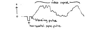
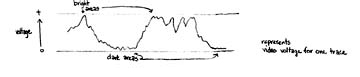
Representative of one trace. Horizontal sync to begin trace. Video signal fluctuations to compose the trace
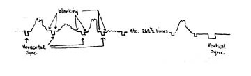
Representative of one field
Horizontal sync pulses to begin 262 ½ traces
Vertical sync pulse to begin next field
Video signal fluctuations to compose each trace
Blanking pulse: prevents visibility of retrace, when beam returns from right to left to begin scanning of next line and when beam returns to top after field is scanned.
SYNC
Synchronization: to be contemporary with.
Refers to the process which maintains the timing and the rate of the scanning process. It insures that both the camera and the monitor begin to scan simultaneously, begin each line and field at the same time and that the rate for both is the same. If sync were not present, the image displayed on the monitor would not be readable as an image. In any video system there must be a sync source. In a single camera system, sync may be generated by the camera or by the deck, but not by both at the same time. In a multiple camera system, the cameras must have one common sync source; usually the sync is generated by a sync generator within the video mixing machine. A separate sync generator may also be used. Sync pulses are produced by oscillators oscillating at specific frequencies.
There are two elements to sync:
horizontal sync maintains the side to side orientation. Loss produces diagonal lines.
vertical sync maintains top to bottom orientaion. Loss produces rolling.
There are two types of sync:
random sync where only horizontal sync is supplied; this results in traces on the monitor which are not evenly spaced
2: 1 sync or interlace wherein the traces are evenly spaced
Sync pulses are also recorded on video tape along with video information so that on playback the sync track is read by the monitor and the image displayed approximated the image the camera recorded.
A horizontal sync pulse is generated at the beginning of each horizontal trace.
A vertical sync pulse is generated between fields


