Obsolete Technology Tellye !
True Televisions have the CRT Tube !!
Welcome to the Obsolete Technology Tellye Web Museum. Here you will see a Museum showing many Old Tube Television sets
all with the CRT Tube, B/W ,color, Digital, and 100HZ Scan rate, Tubes technology. This is the opportunity on the WEB to see, one more time, what real technology WAS ! In the mean time watch some crappy lcd picture around shop centers (but don't buy them, or money lost) !!!
Obsolete Technology Tellye !
True Televisions have the CRT Tube !! Welcome to the Obsolete Technology Tellye Web Museum. Here you will see a Museum showing many Old Tube Television sets all with the CRT Tube, B/W ,color, Digital, and 100HZ Scan rate, Tubes technology. This is the opportunity on the WEB to see, one more time, what real technology WAS ! In the mean time watch some crappy lcd picture around shop centers (but don't buy them, or money lost) !!!
Richtige Fernseher haben Röhren!
How to use the site:
- If you landed here via any Search Engine, you will get what you searched for and you can search more using the search this blog feature provided by Google. You can visit more posts scrolling the left blog archive of all posts of the month/year,
or you can click on the main photo-page to start from the main page. It starts from the most recent post to the older post simple clicking on the Older Post button on the bottom of each page after reading , post after post.
You can even visit all posts, time to time, reaching the bottom end of each page then click on the Older Post button.
- If you arrived here at the main page via bookmark you can visit all the site scrolling the left blog archive of all posts of the month/year pointing were you want , or more simple You can even visit all blog posts, from newer to older, clicking at the end of each bottom page on the Older Post button.
So you can see all the blog/site content surfing all pages in it.
- The search this blog feature provided by Google is a real search engine. If you're pointing particular things it will search IT for you; or you can place a brand name in the search query at your choice and visit all results page by page. It's useful since the content of the site is very large.
Note that if you don't find what you searched for, try it after a period of time; the site is a never ending job !
Every CRT Television saved let revive knowledge, thoughts, moments of the past life which will never return again.........
Don't forget the past, the end of the world is upon us! Pretty soon it will all turn to dust!
Have big FUN ! !
©2010, 2011 Frank Sharp - You do not have permission to copy photos and words from this blog, and any content may be never used it for auctions or commercial purposes, however feel free to post anything you see here with a courtesy link back, btw a link to the original post here , is mandatory.
All sets and apparates appearing here are property of
Engineer Frank Sharp. NOTHING HERE IS FOR SALE !
600.000 PAGEVIEWS - VISITS. THE WAY TO A MILLION GOING FORWARD !
TODAY.............................................
Obsolete Technology Tellye !
Have reached the 600000 pageview / visit.

THE HALF WAY TO A MILLION GOING FORWARDED BY 100000 !!
THANK YOU !
FRANK SHARP.
Have big FUN ! !
©2010, 2011, 2012, 2013 Frank Sharp - You do not have permission to copy photos and words from this blog, and any content may be never used it for auctions or commercial purposes, however feel free to post anything you see here with a courtesy link back, btw a link to the original post here , is mandatory.
All sets and apparates appearing here are property of
Engineer Frank Sharp. NOTHING HERE IS FOR SALE !
-----------------------------------------------------------------------
Richtige Fernseher haben Röhren!
----------------------------------------------------------------------------
MOST POPULAR POSTS OF EVER:
FIGURE 91.1 Example of a typical CRT with electromagnetic focus, and electromagnetic deflection. This type of tube d...
The supply is based on MOTOROLA MC44603p which is a MIXED FREQUENCY MODE GR...
The GRUNDIG SUPER COLOR 8642 is A 26 Inches (66Cm) GRUNDI...
SONY KV-1484MT CHASSIS SCC-D26A-A CRT TUBE SONY TRINITRON A34JBU10X VIEW.
CRT TUBE SONY TRINITRON A34JBU10X VIEW. ...
A Top television set with top features...
The PHILIPS 25ML8766/08B IDTV 100HZ MATCH LINE is Another top series mod...
GENERAL Circuit Description for ITT DIGI...
GRUNDIG SUPER COLOR C 2404 SERIE F 3015 CHASSIS CUC 51KT PCB (EINBAU-CHASSIS 29701-030...) VIEW
SOUND BOARD 450918-9 6611 37 27 ITT DIGIVI...
The THOMSON CHASSIS ICC5 Is a highly engineered ...
---------------------------------------------------------
MOST POPULAR POSTS OF THE MONTH:
CATHODE RAY TUBE DISPLAYS CASE STUDY: CRT ELECTRON TUBE.
FIGURE 91.1 Example of a typical CRT with electromagnetic focus, and electromagnetic deflection. This type of tube d...
ITT NOKIA DIGIVISION 7170 VT CHASSIS DIGI B-E INTERNAL VIEW.
GENERAL Circuit Description for ITT DIGI...
NORDMENDE COLOR 3636 CC3 7.514 (THOMSON) CHASSIS F14 (THOMSON ICC4) INTERNAL VIEW.
The set is based on the ...
GRUNDIG SUPER COLOR 8642 YEAR 1978.
The GRUNDIG SUPER COLOR 8642 is A 26 Inches (66Cm) GRUNDI...
SAMSUNG MOD:CZ-6844W YEAR 2001.
The SAMSUNG MOD:CZ-6844W is a 28 inches (70cm) DIGITAL color television with 99 programs,OSD, STEREO DIGITAL SOUND, TELETEXT, 120...
GRUNDIG XS70/1 CHASSIS CUC6360 (29701-088) INTERNAL VIEW.
GRUNDIG XS70/1 CHASSIS CUC6360 (29701-088) : CPU - XC68HC11F1B4 EEPROM...
PHILIPS 14PT1562 CHASSIS L6.1 INTERNAL VIEW.
The PHILIPS CHASSIS L6 is the most compact mini chassis for a color tv. The chassis was even featured for a 110° degree crt tu...
ITT IDEAL COLOR 3426 OSCAR TUNER (5430 62) CHASSIS COMPACT B 110° S4-SQ / IFB-491 D F Tuning Controls View.
ITT IDEAL COLOR 3426 CHASSIS COMPACT B 110° S4-SQ / IFB-491 D F - Tuning Controls View. Cont...
PHILIPS 25ML8766/08B IDTV 100HZ MATCH LINE YEAR 1992.
The PHILIPS 25ML8766/08B IDTV 100HZ MATCH LINE is Another top series mod...
TELEFUNKEN PALCOLOR 5600 SUPERCONTROL YEAR 1976.
The TELEFUNKEN PALCOLOR 5600 SUPERCONTROL is a 20 inches color television with 12 programs and infra red remote control. Tunin...
---------------------------------------------------------
MOST POPULAR POSTS OF THE WEEK:
CATHODE RAY TUBE DISPLAYS CASE STUDY: CRT ELECTRON TUBE.
FIGURE 91.1 Example of a typical CRT with electromagnetic focus, and electromagnetic deflection. This type of tube d...
The PHILIPS 14CT3205 PHILETTA COLOR is a 14 inches (37cm) Portable color television with 12 programs. The set has a rem...
GRUNDIG COLOR 5050 ULTRA ELECTRONIC YEAR 1972.
THE GRUNDIG COLOR 5050 ULTRA ELECTRONIC is a 26 inches color television with 7 programs sensor button changer and potentiometers t...
NORDMENDE COLOR 3636 CC3 7.514 (THOMSON) CHASSIS F14 (THOMSON ICC4) INTERNAL VIEW.
The set is based on the ...
ITT NOKIA DIGIVISION 7170 VT CHASSIS DIGI B-E INTERNAL VIEW.
GENERAL Circuit Description for ITT DIGI...
FERGUSON Mod. 38030 YEAR 1986
The FERGUSON Mod. 38030 is a portable 12 inches B/W Screen with ONLY UHF Channels reception capability. marketed with the FERGUSO...
PHILIPS 14PT1562 CHASSIS L6.1 INTERNAL VIEW.
The PHILIPS CHASSIS L6 is the most compact mini chassis for a color tv. The chassis was even featured for a 110° degree crt tu...
TELEFUNKEN PALCOLOR HIFI 292 PIP "MILLENNIUM" CHASSIS 618 A-2 PIP (ICC5341) UNITS VIEW.
...
GRUNDIG XS70/1 CHASSIS CUC6360 (29701-088) INTERNAL VIEW.
GRUNDIG XS70/1 CHASSIS CUC6360 (29701-088) : CPU - XC68HC11F1B4 EEPROM...
SAMSUNG MOD:CZ-6844W YEAR 2001.
The SAMSUNG MOD:CZ-6844W is a 28 inches (70cm) DIGITAL color television with 99 programs,OSD, STEREO DIGITAL SOUND, TELETEXT, 120...
-------------------------------------------------------------------------
Every CRT Television saved let revive knowledge, thoughts, moments of the past life which will never return again.........
Don't forget the past, the end of the world is upon us! Pretty soon it will all turn to dust!
Posted By: FRANK a
3:00 AM 0 comments:  Email ThisBlogThis!Share to TwitterShare to Facebook
TAG:
2013,
news,
Obsolete Technology Information
WEDNESDAY, SEPTEMBER 4, 2013
NORDMENDE SPECTRA COLOR SC1032 YEAR 1978.
======================================================
========================================================================
The NORDMENDE SPECTRA COLOR SC1032 is a 22 inches (56cm) color television with 12 programs manual push button change and potentiometric tuning search system.
The set is slightly rare because of the manual program / tuning feature and therefore fitting it as a second choice after those remote controlled models already present in NORDMENDE production in that era.
It features a Videocolor (RCA) PIL CRT TUBE, and a modular chassis F6TT.
The NORDMENDE SPECTRA COLOR SC1032 has anyway a 12 digit led display showing program numbers.
All commands are manual for volume, color, bright, contrast + power switch without the NORDMENDE famous child-lock.
(To see the Internal Chassis Just click on Older Post Button on bottom page, that's simple !)
Nordmende was a manufacturer of entertainment electronics based in Bremen, Germany.
The original company, Radio H. Mende & Co, was founded in 1923 by Otto Hermann Mende (1885-1940) in Dresden. Following the destruction of the plant during the bombing raids in 1945, Martin Mende (the founder's son) created a new company in Bremen in 1947, in a former Focke-Wulf plant, under the name North German Mende Broadcast GmbH. The name was subsequently changed to Nordmende: subsequently the company became one of the prominent German manufacturers of radios, televisions, tape recorders and record players in the 1950s and 1960s.
In the 1970s, Nordmende televisions were renowned for their innovative chassis, and for the rigorous testing and quality control of their finished products. Both created high costs, however, which soon proved a competitive disadvantage when the price of colour televisions began to plunge.
In 1969, Mende's sons took over the company, and in 1977 a majority shareholding was sold to the French Thomson Brandt company and the chassis remains the original NordMende until CHASSIS F9. The following year, the family sold their remaining shares to Thomson. In the 1980s, the factories in Bremen were closed, Nordmende becoming purely a Thomson trademark (Starting from chassis F10 F11 they're all THOMSON).
In the 1990s, the name Nordmende was used with decreasing frequency, and it eventually disappeared in favour of the Thomson name. In 2005 Videocon Group acquired all cathode ray tube activities from Thomson. This led to the creation of VDC Technologies, which manufactures TV sets using the Nordmende brand under licence from Thomson.
The Nordmende brand name was relaunched in Ireland in September 2008 by the KAL Group. Although

Nordmende was well known for its televisions throughout Ireland during the 1970s and 1980s, the company bought the rights to the name and launched a range of white goods including fridges, freezers, washing machines, and dishwashers, alongside a revamped range of flat-screen TVs and stereos.
NORDMENDE HISTORY IN GERMAN:
Die Vorkriegsgeschichte findet sich unter Mende. Nach dem Totalverlust in Dresden gründet Martin Mende (30.12.1898-1982) unter Mitwirkung von Hermann Weber am 26. August 1947 [FT5901] in Bremen-Hemelingen die Norddeutsche Mende-Rundfunk GmbH.
Die ersten Gehäuse liefert ein Tischler in Achim gegen Kompensation von fünf Gehäusen zu einem Rundfunkgerät. Der frühere Mende-Konstrukteur, Obering. Heer zeichnet wieder für die Geräte verantwortlich [FT49??].
Ab 27. Juli 1948 liefert die neue, zuerst 18 und bald 60 Personen umfassende Firma auf Grund von Währungsreform, Krediten und Zulieferverträgen die neue Radioproduktion.
Das Regime in Ostdeutschland lässt den Namen Mende nicht zu, so dass Martin Mende mit grafischen Konstruktionen im Zusammenhang mit «Nord» an seinen Vorkriegserfolg anschliesst.
Die Hallen der ehemaligen Focke-Wulf AG beim Bahnhof Seebaldsbrück dienen als Werkstätten. 1950 beschäftigt das Unternehmen 700, 1959 schon 3500 und im Zenit 6300 Personen.
1950 beginnt die Firma mit UKW-, 1953 mit Fernseh- und 1954 mit Mess- und Prüfgeräten. Gegen Ende der 50er Jahre heisst die Firma Norddeutsche Mende Rundfunk KG [RP7901].
Nachdem sich Nordmende bislang nicht mit Magnettongeräten befasst hat, bringt das Werk 1958 das erste deutsche Heim-Tonbandgerät mit drei Motoren auf den Markt. Allerdings dominieren auf diesem Sektor eindeutig andere Firmen wie AEG/Telefunken und Grundig. Von Nordmende kommen jeweils nur ein bis zwei Geräte (1960 keines) in die Kataloge. Dafür hat die Firma Erfolg mit einem anderen Neueinstieg:
1958 stellt Nordmende mit «Mambo» ihr erstes Reisegerät vor - aber nicht «das erste deutsche, serienmässig hergestellte und volltransistorisierte Koffergerät», wie man aus einer Quelle nachlesen kann. Danach wird Nordmende in Deutschland auf dem Sektor Reisegeräte besonders stark, obwohl sie keine Röhren-Koffer baute. Immerhin kosten die in «Mambo» verwendeten 8 Halbleiter dann im Einzelhandel DM 98.70, während für die vier D-Röhren der 90er-Serie - auch zum Katalogpreis - etwa DM 35.- auszugeben wären. Preis des ganzen Gerätes: DM 189.- plus zwei Flachbatterien von 4,5 V.
Bis 1969 gibt es ca. 92 Modelle der tragbaren Radios (Koffer- bzw. «Handradios», d.h. «Hand held radios»). Beispielsweise finden sich im Katalog 1961/62 [448] je 11 Tischradios und Radiomöbel sowie 8 Modelle von Reiseradios. 17 verschiedene Fernsehmodelle zeigen dagegen, wo in jener Zeit der Erfolg zu holen war.
Gemäss [FT7901] liegt Nordmende während kurzer Zeit mit der sogenannten «Tippomatik-Bedienung» sogar technisch vorne. Siehe auch Philips etc.
Auch Konzertschränke scheinen Ende der 50er bis Anfang 60er Jahre eine tragende Säule für Nordmende zu sein. Dabei verwendet die Firma immer wieder gleiche Namen wie «Cabinet», «Caruso», «Casino», «Cosima» sowie «Arabella» und «Isobella» mit wechselnden Zusatz-Nummern oder den Zusatz «Stereo», z.B. in den Jahren 1959 und 1960/61.
Im März 1967 nimmt das Werk die Produktion von Farbfernsehgeräten auf. Zum Firmenjubiläum erscheint eine Gerätereihe mit der Bezeichnung 'Goldene 20'. 1969 übernehmen die Mende-Söhne Karl und Hermann die Geschäftsführung.
1977 führt der verschärfte Wettbewerb zum Verkauf der Mehrheit an den französischen Konzern Thomson-Brandt; die Familie Mende zieht sich anschliessend ganz aus dem Unternehmen zurück. Martin Mende stirbt 1982.
Posted By: FRANK a
4:00 PM 0 comments:
Email ThisBlogThis!Share to TwitterShare to Facebook
TAG:
1978,
color,
F6TT,
Germany,
modular,
Nordmende,
Old Vintage Television,
pil,
RCA,
Videocolor
NORDMENDE SPECTRA COLOR SC1032 CHASSIS F6TT INTERNAL VIEW.
NORDMENDE SPECTRA COLOR SC1032 CHASSIS F6TT Controlled power supply for a television receiver equipped with remote control:BLAUPUNKT SWITCH MODE POWER SUPPLY.Blaupunkt-Werke GmbH (Hildesheim, DT)
NORDMENDE SPECTRA COLOR Chassis F6TT Power Supply view.
SMPS supply with S2530A (TOSHIBA) Chassis F6TT Power Supply view.
A single isolation transformer supplies both the remote control receiver and the television receiver. A pulse generator such as a blocking oscillator which energizes the primary winding of the isolation transformer has its pulse width controlled in response to the loading of the circuit of the secondary winding of the isolation transformer, as measured by the voltage across a resistor in the circuit of a primary winding. This measuring resistor is interposed between the emitter of the switching transistor of the blocking oscillator and the receiver chassis. A transistor switching circuit for cutting off the low voltage supply to the scanning circuit oscillators of the television receiver is responsive to the output of the remote control receiver, to a signal from an operating control of the television receiver, and to an indication of overcurrent in the picture tube, independently.
1. A power supply circuit for a television receiver equipped for remote control comprising, in combination:
an on-off switch for connecting and disconnecting the television receiver and its power supply circuit respectively to and from the electricity supply mains;
pulse generating means arranged for energization through said on-off switch;
an isolation transformer having its primary winding supplied with the output of said pulse generating means;
a power conversion circuit connected to the secondary winding of said isolation transformer for energization thereby, for supplying an operating voltage for the scanning circuits of the television receiver and for supplying a plurality of other voltages to said receiver, at least one of which other voltages is also supplied to said scanning circuits;

a remote control signal receiver for remote control of said television receiver and controlled switching means responsive to said remote control receiver for switching said television receiver between a stand-by condition and an operating condition, both said remote control receiver and said controlled switching means being connected to a secondary winding of said isolation transformer for energization thereby, said controlled switching means having a switching path for connecting and disconnecting said scanning circuits of said television receiver respectively to and from a source of said operating voltage in said power conversion circuit and
means for reducing energy transfer through said pulse generating means to said isolation transformer when said television receiver is in the stand-by condition.
2. A power supply circuit as defined in claim 1, in which said pulse generating means includes rectifying means energized through said on-off switch for supplying direct current for energization of said pulse generating means. 3. A power supply circuit as defined in claim 2, in which said energy transfer reducing means includes means for varying the width (duration) of pulses generated by said pulse generating means in response to the extent of loading of the secondary circuit of said isolating transformer as measured in the primary circuit of said transformer. 4. A power supply circuit as defined in claim 2, in which said pulse generating means includes a blocking oscillator and said energy transfer reducing means includes means for reducing the width (duration) of the pulses generated by said blocking oscillator. 5. A power supply circuit as defined in claim 4, in which said blocking oscillator includes a switching transistor (5) and a load measuring resistor (7) interposed in a connection between the emitter of said switching transistor and the receiver chassis, and in which said pulse width reducing means is responsive to the voltage drop across said load measuring resistor. 6. A power supply circuit as defined in claim 5, in which said pulse width reducing means includes a controllable resistance (10) in the circuit of said blocking oscillator controlled in response to the voltage drop across said load measuring resistor. 7. A power supply circuit as defined in claim 1, in which said operating voltage connected and disconnected to said scanning circuits by said controlled switching means is the low voltage supply voltage (U 3') of the line scan and picture scan oscillators of the television receiver and in which said controlled switching means is controlled so as to switch off said low voltage supply voltage to put the television receiver in the stand-by condition. 8. A power supply circuit as defined in claim 7, in which said controlled switching means includes a first switching transistor (15) at the collector of which there is applied a direct current supply voltage (U 3) energized through said isolating transformer and a second switching transistor (24) for controllably short-circuiting the base bias of said first switching transistor, whereby a stabilized low voltage (U 3') exists at the emitter of said first switching transistor (15) when a positive signal is supplied from an operating control of the television receiver or from said remote control receiver to the base of said second switching transistor (24). 9. A power supply circuit as defined in claim 7, in which said controlled switching means is responsive independently to an overcurrent condition in the picture tube for switching off said low voltage supply voltage (U 3') in response to said overcurrent condition.
Description:
The present invention relates to a power supply unit including a blocking oscillator for utilization with a television receiver provided with ultrasonic remote control, and more particularly to a television receiver the operating conditions of which are normal operation, a stand-by operation, and the turned-off condition, and a power supply unit therefor that includes an isolating transformer.
In recent times television receivers have frequently been provided with ultrasonic remote control devices for the purpose of offering easier control. As more and more television receivers are utilized in combination with additional equipment, it becomes increasingly necessary to connect the receivers only indirectly to the electric power mains (house wiring). In a known advantageous solution of this problem, a power supply unit includes an isolating transformer which is wired up with a blocking oscillator in the primary circuit. The blocking oscillator is supplied with a d-c voltage which is obtained by rectification of the supply voltage. Compared to the isolating transformers which are directly mains-operated, these so-called switch-mode power supply units have the advantage that they can be made in considerably smaller size, as they are operated at a significantly higher frequency, and the further advantage that they require less expensive means for rectification.
It is necessary to supply television receivers equipped with ultrasonic remote control with the possibility for a stand-by operation in which only the ultransonic receiver is supplied with power and, in some cases, also the heating current for the picture tube. Usually a separate power supply unit is provided for the ultrasonic receiver and the heating of the picture tube, a unit that includes an isolating transformer of its own, the primary winding of which is directly mains-fed. Upon transition from normal operation to stand-by operation, the power supply unit of the blocking osciallator is switched off, so that the television receiver receives only the relatively small quantity of energy required for the ultrasonic receiver and, in some cases, also for the heating of the picture tube.
Because of the required second isolating transformer, this known circuit has the disadvantages that it requires both greater space and greater expenditure.
It is the object of the present invention to develop a simplified power supply unit which does not have the above-mentioned disadvantages.
SUMMARY OF THE INVENTION
Briefly, the television receiver and the ultrasonic receiver are connected to the same isolating transformer; means for the switching from normal operation to stand-by operation and vice versa are placed in the secondary circuit of the isolating transformer, and means are arranged in the primary circuits of the isolating transformer for reducing the amount of energy made available for stand-by operation purposes.
The main advantages of the present invention are that no separate isolating transformer is required for supplying the current during the stand-by operation, and that, during the stand-by operation, it is nevertheless only the power required for this operation which is consumed.
An advantageous embodiment of the present invention obtains reduction of the energy quantum transmitted through the power supply during stand-by by reduction of the pulse width of the pulses generated by the blocking oscillator.
Another advantageous embodiment of the present invention utilizes measurement in the primary circuit of the isolating transformer of variation in load occurring in the secondary circuit as a control variable for determining the pulse width.
A further advantageous embodiment of the present invention obtains the control variable for the pulse width across a measuring resistor interposed in the connection of the emitter of the switching transistor of the blocking oscillator to the chassis.
Still another advantageous embodiment of the present invention provides that the voltage drop across the measuring resistor controls a controllable resistor.
The advantageous embodiments described above offer highly simple and advantageous possibilities for measuring the variation in load upon switching between normal and stand-by operation, as well as for the consequent control of the energy transmitted via the isolating transformer.
The possibility of a simple and inexpensive switching between normal and stand-by operation is achieved by effecting the switching between normal and stand-by operation by means of switching on or switching off, respectively, the low voltage supply of the line scan oscillator, and, especially, by a first switching transistor which short-circuits the base bias of a second switching transistor at the collector of which a direct current supply voltage is present and at the emitter of which a stabilized low voltage exists, when a positive signal is supplied from the operating control of the television receiver or from the remote control receiver to the base of the first switching transistor.
The circuit arrangements just mentioned offer the advantage that they may simultaneously be utilized as a protective circuit. This is achieved by a switching-off device for the low voltage which can also be triggered at any time by a signal built up by overcurrent in the picture tube.
BRIEF DESCRIPTION OF THE DRAWINGS
The invention is further described by way of illustrative example by reference to the annexed drawings in which:
FIG. 1 is a circuit diagram, partly in block form, of an embodiment of the invention;
FIG. 2 is a circuit diagram of one form of means for interrupting the power to the picture circuits in the stand-by condition in connection with the circuit of FIG. 1, and
FIG. 3 is a circuit diagram of one way of controlling the pulse width of the blocking oscillator 4 in response to the switching circuit 8 in the circuit of FIG. 1.
DESCRIPTION OF THE PREFERRED EMBODIMENT

An on-off power switch 2 of the television receiver is connected to the supply terminals 1, providing a primary operating control for the receiver. Consquently, the supply voltage is also present at the output of the operating control 2 when the television receiver is turned on thereby, and arrives at a rectifying stage 3 comprising means for rectifying and smoothing the supply current as well as for suppressing interference. A d-c voltage, feeding a blocking oscillator stage 4, is present at the output of the recifying stage 3. The main part of the blocking oscillator 4, symbolically represented in FIG. 1 by a fragmentary circuit diagram, is a switching transistor 5, in the load circuit of which the primary winding of an isolating tranformer 6 is placed. A measuring resistor 7 is connected between the emitter of the switching transistor 5 and the chassis, across which measuring resistor a voltage is taken and applied to a load-dependent control circuit 8. The voltage taken at the measuring resistor 7 is fed via a resistor 9 to the base of a transistor 10 which serves as a controllable load for the blocking oscillator 4. A resistor 11 and a capacitor 12, each of which is connected to chassis with its other terminal, are also connected to the base of the transistor 10. The emitter of transistor 10 is connected to chassis, while the collector of the transistor 10 is connected back to the blocking oscillator stage 4.
In the secondary circuit of the isolating transformer 6, a d-c voltage supply stage or power conversion circuit 13 is placed, substantially consisting of a rectifying circuit 14, which, in the example shown, is provided with six outputs at which the voltages U 1 to U 5 can be taken off with respect to the sixth output connected to the chassis. At the terminal U 3, there is, in addition, a branch feeding both the collector-to-emitter path of the transistor 15 and also, through a resistor 16, the collector-to-emitter path of the transistor 15a. The emitter of the transistor 15a is directly connected to the base of transistor 15. The emitter of the transistor 15 is connected to chassis via a series connection of a resistor 17, a potentiometer 18, and a further resistor 19. The tap of the potentiometer 18 is connected to the base of a further transistor 20. The transistor 20 is connected to chassis by means of its emitter via a Zener diode 21, the collector of the transistor 20 controlling the base of the transistor 15a. The emitter of the transistor 20 is connected to the emitter of the transistor 15 via a resistor 22. A terminal for tapping off the voltage U 3' is connected to the emitter of the transistor 15.
The base of the transistor 15a is connected to a switching stage 23 responsive to a remote control ultrasonic receiver by a conductor leading to the collector of a switching transistor 24 which is connected to chassis via its emitter. The base of the switching transistor 24 is connected to an input terminal 28 leading into the television receiver via two resistors 25, 26 and a capacitor 27 connected in series, that input terminal 28 passing on switching signals from the receiver to the switching transistor 24, as will be explained in more detail below.
The cathode of a diode 29, which is connected to chassis via its anode, is connected to the junction point of the resistor 26 and the capacitor 27. The junction point of the two resistors 25, 26 is connected to chassis via a capacitor 30. The base of the switching transistor 24 is connected to chassis via a resistor 31. Furthermore, that base electrode is also connected to a terminal 32 to which an electrical switching signal is applied which is either built up in response to an ultrasonic signal received by the remote control receiver 32' or is supplied from an operating control of the television receiver. At the terminal 32, the switching transistor 24 receives the signal containing the information whether the television receiver is to work in the normal operating condition, i.e. to receive and process the sound and video signals, or in the stand-by condition in which it is substantially only the ultrasonic receiver that is supplied with current.
When a positive signal arrives at the base of the switching transistor 24, the latter becomes conductive, and causes chassis potential to be present at the base of transistor 15a. The transistor 15 is thereby blocked, and there is no longer any voltage at the terminal U 3'. Since the voltage U 3' serves as an operating voltage for the line and picture scan oscillator, the deflecting stages of the receiver cannot work and no high voltage and other related supply voltages are generated at the line circuit transformer. In consequence, by means
illustrated diagrammatically in FIG. 2,
the electric circuits connected to the terminals U 1 to U 3 are interrupted. The voltages U 4 and U 5 serve for supplying the ultrasonic receiver, i.e. they are required for the stand-by operation.
In case no counteracting means should be provided for, the variation in load would cause a voltage rise in the secondary circuit of the isolating transformer 6, which effect is, of course, not desired. Therefore, a measuring resistor is connected in the primary circuit in the emitter line of the switching transistor 5 of the blocking oscillator 6, the variation in load in the secondary circuit appearing at the measuring resistor 7 as a current variation. The current change thus produced, causes a variation in the base bias of the transistor 10, the capacitor 12 having an integrating effect to avoid undesired effects due to interference pulses and abrupt load fluctuations.
The change of the working point of the transistor 10 causes a change in the pulse width in the blocking oscillator stage 4, as more fully shown in FIG. 3, so that the energy quantum transmitted via the isolating transformer 6 is such that the required voltages are present in the secondary circuit. It should also be mentioned that the load-dependent switch 8 and the circuit of FIG. 3 are represented only by way of illustration and that many circuit arrangements may be devised by straight-forward application of known principles for controlling the pulse width.
The circuit connected between the terminal 28 and the base of the switching transistor 24 serves as a part of a protective circuit for the picture tube. Any overcurrent is measured at the low-end resistor 31 of the high-voltage cascade in conventional techinque. The voltage thus produced is fed to the base of the switching transistor 24, and causes the television receiver to be switched over to stand-by operation, so that no damage can be done to the picture tube. Thus, the device performing the switching between normal operation and stand-by operation is advantageously and simultaneously utilized as a protective circuit. The circuit 23, as shown, provides for stabilizing the potential at the base of transistor 24 and for integrating such possibly occurring overload peaks as are not intended to triggering the protective circuit.
Using the circuit diagram according to FIG. 3 it is possible in a simple manner to control the pulse width of the blocking oscillator 4 in response to the switching circuit 8.
According to the circuit diagram of FIG. 2 the terminal U1 is connected to a line scan oscillator circuit 40, the terminal U2 to a picture scan oscillator circuit 41 and the terminal U3 to a circuit 42 for a sound output stage. The circuits 40, 41, 42 get their operating voltage from the terminal U3'. If the operating voltage U3' is zero, the circuits 40, 41, 42 are interrupted. In this case the voltages at the terminals U1, U2, U3 remain.
The described circuit of this invention for controlling the voltage in the secondary circuit of the isolating transformer 6 offers the advantage that it is exclusively arranged in the primary circuit, and, therefore, permits an uncomplicated design which is easy to realize. To control the pulse width by measuring the load fluctuations at the low-end resistor of the switching transistor 5, represents a very useful means for control since, thereby the transmitted energy can effectively and easily be controlled.
The blocking oscillator stage 4 shown in detail in FIG. 3 incorporates an externally triggered blocking oscillator arranged to be triggered through an oscillator operating preferably at the line scanning frequency, which is to say its wave form is not particularly critical and it should be provided with means to keep it in step with the line scanning frequency, as is known to be desirable. The transistors 51 and 52 of the triggered output stage of the blocking oscillator circuit could be regarded as constituting a differential amplifier the inputs of which are defined by the base connections of the respective transistors 51 and 52. The input voltage applied to the base connection of transistor 52 is the Zener voltage of the Zener diode 53, thus a constant reference voltage. The operating voltage for the transistors 51 and 52 and for the Zener diode 53 is obtained from the supply voltage UB, which is to say from the rectifier 3. The diode 67 protects the transistor 52, for example at the time of the apparatus being switched on, against damage from an excessively high emitter-base blocking voltage. The capacitor 65 prevents undesired oscillation of the circuit of transistors 51 and 52, which could give rise to undesired disturbances.
At the base of the transistor 51, there is present as input voltage for the circuit a composite voltage that is the sum of three voltages. These are, first, the line scan frequency trigger voltage coupled through the capacitor 63; second, a bias voltage dependent upon the loading of the blocking oscillator stage resulting from the load on the secondary of the transformer 6, but detected by the voltage across the resistor 7 and actually controlled by the load-sensitive control circuit 8, and, third, a regulating voltage applied at the terminal 71 of the resistor 70, which regulating voltage is proportional to the voltage of the secondary winding of the transformer 6 and can accordingly be provided by one or another of the output circuits of the rectifier 14 of FIG. 1 or by a separate winding of the transformer 6 and a separate rectifier element connected in circuit therewith. This regulating voltage and the control voltage provided by the control circuit 8 are applied to the resistor 61 which completes the circuit for both of these bias voltages and their combined effect constitutes the bias voltage for the transistor 51 which determines its working point.
The circuit of the transistors 51 and 52 operates as an overdriven differential amplifier. When the trigger voltage exceeds the threshold determined by the base voltage of the transistor 51, the circuit produces an approximately rectangular output voltage pulse of constant amplitude. Since the trigger voltage is recurrent, the result is a periodic succession of rectangular output voltage pulses, but the duration or pulse width of these pulses depends upon the loading and the output voltage of the stage. The output voltage of the circuit constituted by the transistors 51 and 52 comes from the emitter connection of the transistor 52 and is furnished to the switching transistor 5, preferably through a driver stage 54, such as a transformer or another transistor stage for better matching of the circuit impedances. Of course, the collector circuit of the transistor 5 includes the primary winding of the transformer 6 of FIG. 1.

The described power supply unit thus represents a well functioning component subject to but a small number of potential sources of error, due to the simple design, and permits considerable reduction of costs in comparison with circuits and equipment heretofore known.
NORDMENDE Chassis F6TT
Detail viewing:
- Line deflection output + EHT + Tripler
- Line deflection output Transistor BU208 (Telefunken)
- Frame deflection output Unit in place + N/S Raster correction components circuitry.
- Signal processing section - IF + Sound + Synch + Luminance + Chrominance + RGB Amplifiers
BU208(A)
Silicon NPN
npn transistors,pnp transistors,transistors
Category: NPN Transistor, Transistor
MHz: <1 MHz
Amps: 5A
Volts: 1500V
HIGH VOLTAGE CAPABILITY
JEDEC TO-3 METAL CASE.
DESCRIPTION
The BU208A, BU508A and BU508AFI are
manufactured using Multiepitaxial Mesa
technology for cost-effective high performance
and use a Hollow Emitter structure to enhance
switching speeds.
APPLICATIONS:
* HORIZONTAL DEFLECTION FOR COLOUR TV With 110° or even 90° degree of deflection angle.
ABSOLUTE MAXIMUM RATINGS
Symbol Parameter Value Unit
VCES Collector-Emit ter Voltage (VBE = 0) 1500 V
VCEO Collector-Emit ter Voltage (IB = 0) 700 V
VEBO Emitter-Base Voltage (IC = 0) 10 V
IC Collector Current 8 A
ICM Collector Peak Current (tp < 5 ms) 15 A
TO - 3 TO - 218 ISOWATT218
Ptot Total Dissipation at Tc = 25 oC 150 125 50 W
Tstg Storage Temperature -65 to 175 -65 to 150 -65 to 150 oC
Tj Max. Operating Junction Temperature 175 150 150 °C
Chassis F6TT UNITS view.
- Luminance + Chrominance unit 492.045 G8 with TDA2500/3 + TDA2522 (all PHILIPS)
(Note the long luminance delay line)
- Synchronization Unit with TDA2593 (PHILIPS) 492.174 G10
- Sound - Audio Unit with TBA120U (Telefunken) + L130V (Fairchild Semiconductors) 492.044/E3
- RGB Amplifiers with TBA530 (PHILIPS) 943/K7
- Frame deflection unit 492.225/C1
- E/W Correction Unit 492.213/C
TDA2522 PAL TV CHROMA DEMODULATOR COMBINATION
FAIRCHILD LINEAR INTEGRATED CIRCUIT
GENERAL DESCRIPTION- The TDA2522 is a monolithic integrated circuit designed as
a synchronous demodulator for PAL color television receivers. It includes an 8,8 MHz

oscillator and divider to generate two 4.4 MHz reference signals and provides color difference outputs.
PACKAGE OUTLINE 9B
The TDA2522 is Intended to Interface directly with the TDA2560 with a minimum oF external components. The TDA2530 may be added if RGB drive is required. The TDA2522
is constructed using the Fairchild Planar* process.
TDA2520 COLOUR DEMODULATOR COMBINATION
The TDA2520 is an integrated synchronous demodulator combination for colour television
receivers incorporating the following functions :

~ 8, 8 MHZ oscillator followed by a divider giving two 4, 4 MHZ signals used as reference
signals
- keyed burst phase detector for optimum noise behaviour
- a stage to obtain chrominance signal control (a. c. c.) and an a. c. c. reference level
- a colour killer and identification signal detector
- two synchronous demodulators for the (B-Y) and (R-Y) signals
- temperature compensated emitter follower outputs
- PAL switch
- PAL flip-flop
- integrated capacitors in the symmetrical demodulators reduce unwanted carrier-
signals at the outputs.
TDA2593 SYNCHRO AND HORIZONTAL DEFLECTION CONTROL FOR COLOR TV SETDESCRIPTION
The TDA2593 isa circuit intended for the horizontal
deflectionof color TVsets, suppliedwith transistors
or SCR’S.
.LINE OSCILLATOR(two levels switching)
.PHASE COMPARISON BETWEEN SYNCHRO-
PULSE AND OSCILLATOR VOLTAGE
Ø 1, ENABLED BY AN INTERNAL PULSE,
(better parasitic immunity)
.PHASE COMPARISON BETWEEN THE FLYBACK
PULSES AND THE OSCILLATORVOLTAGE
Ø2
.COINCIDENCE DETECTOR PROVIDING A
LARGE HOLD-IN-RANGE .FILTER CHARACTERISTICS AND GATE
SWITCHING FOR VIDEO RECORDER APPLICATION
.NOISE GATED SYNCHRO SEPARATOR
.FRAME PULSE SEPARATOR
.BLANKING AND SAND CASTLE OUTPUT
PULSES
.HORIZONTAL POWER STAGE PHASE LAGGING
CIRCUIT
.SWITCHING OF CONTROL OUTPUT PULSE
WIDTH
.SEPARATED SUPPLY VOLTAGE OUTPUT
STAGE ALLOWING DIRECT DRIVE OF
SCR’S CIRCUIT .SECURITY CIRCUIT MAKES THE OUTPUT
PULSE SUPPRESSED WHEN LOW SUPPLY
VOLTAGE.
NORDMENDE SPECTRA COLOR SC1032 CHASSIS F6TT COLOR AMPLIFIER WITHConstant bandwidth RGB output amplifiers having simultaneous gain and DC output voltage control :
A color television receiver includes conventional circuitry for processing and detecting a received color television signal. Three chrominance-luminance matrices combine detected color difference and luminance signals forming color red, blue and green video signals. Emitter follower coupling stages apply the color video signals individually to each

of three output amplifiers which in turn drive the cathode electrodes of a unitized gun CRT. Potentiometers couple the emitter electrodes of the output amplifiers to a source of operating potential providing a simultaneous signal gain and DC output voltage adjustment for each amplifier during CRT color temperature setup. A voltage divider controls the voltage applied to the common screen grid electrode of the CRT providing a master setup adjustment.
1. In a color televison receiver, for processing and displaying a received television signal bearing modulation components of picture information, having a cathode ray tube including a trio of electron source means producing individual electron beams impinging an image screen to form three substantially overlying images and in which the respective operating points and relative conduction levels of said electron source means determine the color temperature of the reproduced image, the combination comprising:
master conduction means, coupled to said trio of electron source means simultaneously varying said conduction levels;
a plurality of substantially equal bandwidth amplifiers, each coupled to a different one of said electron source means, separately influencing said conduction levels;
low output impedance signal translation means recovering said picture information and supplying it to each of said plurality of amplifiers; and
separate adjusting means individually coupled to at least two of said amplifiers for simultaneously producing predetermined same sense variations in gain and DC output voltage of its associated amplifier while preserving said bandwidths.
2. The combination set forth in claim 1, wherein the transconductance and cutoff voltage of each of said electron source means bear a predetermined relationship and wherein said simultaneous predetermined variations in gain and DC output voltage are determined by said transconductance-cutoff voltage relationship. 3. The combination set forth in claim 2, wherein said plurality of amplifiers each include a gain and DC output voltage determining impedance and wherein each of said separate adjusting means include:
a variable impedance, coupling said gain and DC output voltage determining impedance of said associated amplifier to a source of bias current and forming a shunt path for signals within said amplifier.
4. The combination set forth in claim 3, wherein each of said electron source means include a cathode electrode and wherein each of said amplifiers include:
a transistor having input, common, and output electrodes, said output electrode being coupled to said electron source means cathode.
5. The combination set forth in claim 4, wherein said gain and DC output voltage determining impedance is coupled to said common electrode. 6. The combination set forth in claim 5, wherein said input, common, and output electrodes of said transistors are defined by base, emitter, and collector electrodes, respectively. 7. The combination set forth in claim 6, wherein said gain and DC output voltage determining impedance includes a resistor coupling said emitter electrode to ground and wherein said variable impedance includes:
a resistive control, having a variable resistance, coupling said emitter electrode to a source of operating potential.
8. The combination set forth in claim 7, wherein said three electron source means include control grid and screen grid electrodes common to said three electron guns and wherein variations of cathode electrode voltages permit changes of said relative conduction levels and said respective operating points. 9. The combination set forth in claim 8, wherein said master conduction means includes a variable bias potential source coupled to said common screen grid electrode.
Description:
BACKGROUND OF THE INVENTION
This invention relates to color television receivers and in particular to cathode ray tubes (CRT) drive systems therefor. Each of the several types of color television cathode ray tubes in current use includes a trio of individual electron sources producing distinct electron beams which are directed toward an image screen formed by areas of colored-light-emitting phosphors deposited on the inner surface of the CRT. The phosphors emit light of a given additive primary color (red, blue or green) when struck by high energy electrons. A "delta" electron gun arrangement, in which the electron sources comprise three electron guns disposed at the vertice
s of an equilateral triangle, having its base oriented in a horizontal plane and its apex above or below the base plane, may be used. Alternatively, the three electron sources may be "in line", that is, positioned in a horizontal line. In either case, the three beams produced are subjected to deflection fields and scan the image screen in both the horizontal and vertical directions thereby forming three substantially overlying rasters.
The phosphor deposits forming the image screen may alternatively comprise round dots, elongated areas, or uninterrupted vertical lines. A parallax barrier or shadow mask, defining apertures generally corresponding to the shape of the phosphor areas, is interposed between the electron guns and the image screen to "shadow" or block each phosphor area from electrons emitted from all but its corresponding electron gun.
A color television signal includes both luminance (monochrome) and chrominance (color) picture components. In the commonly used RGB drive systems the separately processed luminance and chrominance information is matrixed (or combined) before application to the CRT cathodes. Three output amplifiers apply the respective red, blue and green video signals thus produced for controlling the respective electron source currents.
The luminance components have substantially the same effect on all three electron sources whereas the color components are differential in nature, causing relative changes in electron source currents. In the absence of video signals, the combined raster should be a shade of grey. At high gun currents, the grey is very near white and at low settings, it is near black. The "color", commonly called color temperature, of the monochrome raster depends upon the relative contributions of red, blue and green light. At high color temperatures, the raster may appear blue and at low color temperatures it may appear sepia. While the most pleasing color temperature is largely a matter of design preference, ideally the receiver should not change color temperature under high and low brightness nor for high and low frequency picture information.
Generally, the electron sources comprise individual electron guns each including separately adjustable cathode, control grid and screen grid electrodes and a desired color temperature is achieved by adjustment of each electrode voltage during black and white setup. While the exact setup procedure employed varies with the manufacturer and specific CRT configuration, all manufacturers attempt to achieve consistent color temperature throughout the usable range of CRT beam current variations.
A typical color temperature adjustment involves setting the low light color temperature condition of each electron gun by adju

sting its screen grid electrode voltage to produce the required DC conditions between electron guns at minimum beam currents. A high light or dive adjustment at increased CRT beam current is then made to insure consistent color temperature. In receivers utilizing CRT's with separately adjustable screen grid electrode voltages, the drive adjustment may take the form of a minor change in signal gain of the output amplifiers. The process is, in essence, one of configuring the operating points of the three electron guns to conform to three substantially identical output amplifiers.
The recently developed economical "unitized gun" type CRT has a combined electron source structure in which three common control grids and three common screen grids are used with the cathodes being the only electrically separate electrodes. The greatly simplified and more economical unitized gun structure, however, imposes some restrictions on the circuitry used to drive the electron sources. Perhaps most significant is the absence of
the flexibility previously provided by individually adjustable screen grid electrode voltages. Due in part to the inverse relationship between electron source transconductance, which may be thought of as "gain" of the electron source, and cutoff voltage, the typical individual low level color temperature or equal cutoff adjustment described above also performs the additional function of establishing nearly equal transconductances for the three electron sources. As a result only minor relative changes in electron source currents occur at higher CRT beam currents.
Color temperature adjustment in a receiver with a unitized gun CRT involves a somewhat different process, namely, configuring the drive and bias applied to each of the gun cathodes to accommodate differences in relative electron source characteristics which, without the equalizing effect of separate screen electrode adjustments, may be considerable.
Initially television receivers using unitized gun CRT's utilized a variable DC voltage divider operative upon each output amplifier to provide adjustment of the DC cutoff voltage. Drive, or signal gain, adjustment to accommodate differences in electron source transconductances was generally accomplished by separate individual gain controls operative on each of the output amplifiers.
However, the more recently developed unitized gun systems combine the DC voltage (cutoff) and signal gain (drive) adjustments for each electron source by simultaneously varying the signal gain and DC voltage in the same direction in a predetermined relationship. One such system used three CRT coupling networks each of which includes a variable impedance simultaneously operative on both the amplitude of coupled signal and DC voltage. Another system uses a variable collector load impedance for each of the output amplifiers, making use of the changes in amplifier signal gain and DC output voltage resulting from collector load variations.
While such systems provide an adequate range of adjustment to achieve color temperature setup using a reduced number of controls, they often degrade image quality. Ideally, the luminance portion of the signal is applied uniformly to each of the three electron sources. Although the relative signal amplitudes may be varied to accommodate transconductance differences between electron sources, it is desirable that each applied signal be an otherwise identical replica of the others. The variable impedance elements in the voltage divider networks and variable collector loads of the prior art interact with the capacities inherent in the output amplifiers and electron gun structures to produce unequal bandwidths for the different color video signals, which cause color changes in their high frequency components (which correspond to detailed picture information). The resulting effect upon the displayed image is similar in appearance to the well-known "color fringing" or misconvergence effect.
OBJECTS OF THE INVENTION
It is an object of the present invention to provide an improved color television receiver.
It is a further object of this invention to provide a novel CRT color temperature setup system.
SUMMARY OF THE INVENTION
In a color television receiver, for processing and displaying a received television signal bearing modulation components of picture information, a
cathode ray tube includes three electron source means producing individual electron beams which impinge an image screen to form three substantially overlying images. The respective operating points and relative conduction levels of the electron source means determine the color temperature of the reproduced image. Master conduction means, coupled to the three electron source means, simultaneously vary the conduction levels and a plurality of substantially equal bandwidth amplifiers, each coupled to a different one of the electron source means, separately influence the conduction levels. Low output impedance signal translation means recover the picture information and supply it to each of the amplifiers. Separate adjusting means are individually coupled to at least two of the amplifiers for simultaneously producing predetermined variations in the gain and DC output voltage of the amplifiers while preserving the bandwidths.
BRIEF DESCRIPTION OF THE DRAWING
The drawing shows a partial-schematic, partial-block diagram representation of a color television receiver constructed in accordance with the present invention.
DESCRIPTION OF THE PREFERRED EMBODIMENT
Referring to the drawing, a signal processor 10 includes conventional circuitry (not shown) for amplifying a received television signal and detecting
the modulated components of luminance and chrominance information therein. The output of signal processor 10 is coupled to a luminance amplifier 11 and a chrominance processor 30. Luminance amplifier 11 is conventional and includes circuitry controlling brightness and contrast of the luminance signal. The output of luminance amplifier 11 is coupled to three luminance-chrominance matrices 12, 13 and 14. Chrominance processor 30 includes conventional chrominance information detection circuitry for providing three color difference or color-minus-luminance output signals (R-Y, G-Y and B-Y) which are individually coupled to luminance-chrominance matrices 12, 13 and 14, respectively. The signal from luminance amplifier 11 is combined with the color-minus-luminance signals from chrominance processor 30 to form the respective red, green and blue video signals which are coupled to the R, G and B output amplifiers 15, 16 and 17, respectively. The outputs of amplifiers 15, 16 and 17 are coupled to the cathode electrodes 23, 24 and 25, respectively, of a CRT 20 having an image screen 21. A voltage divider, formed by a series combination of resistors 83 and 84, is coupled between a source of operating potential +V2 and ground. The junction of resistors 83 and 84 is connected to a common control grid electrode 28 and to ground by a filter capacitor 85 which provides a signal bypass. A potentiometer 80 and a resistor 81 are series coupled between a source of operating potential +V1 and ground, forming another voltage divider. The junction of potentiometer 80 and resistor 81 is connected to common screen grid electrode 29 and to ground by a bypass capacitor 82. Cathode electrodes 23-25, control grid electrode 28 and screen grid electrode 29 are part of a unitized gun structure in CRT 20 with the control grid and screen grid being common to each of the three electron sources defined by the separate cathode electrodes.
While luminance-chrominance matrices 12 and 13 are shown in block form, it should be understood that they are identical to the detailed structure of matrix 14. Similarly, red output amplifier 15 and green output amplifier 16 are identical to the detailed structure of blue output amplifier 17. Further, the receiver shown is understood to include conventional circuitry for horizontal and vertical electron beam deflection together with means deriving a CRT high voltage accelerating potential, all of which have, for clarity, been omitted from the drawing.
Luminance-chrominance matrix 14 includes a matrix transistor 40 having an emitter electrode 41 coupled to ground by a resistor 55 and by a series combination of resistors 46 and 47, a base electrode 42 coupled to the output of luminance amplifier 11, and a collector electrode 43 coupled to a source of operating potential +V3 by a resistor 45. The B-Y output of chroma processor 30 is connected to the junction of resistors 46 and 47. An emitte
r-follower transistor 50 has an emitter electrode 51 coupled to ground by a resistor 56, a base electrode 52 connected to the collector of matrix transistor 40, and a collector electrode 53 connected to +V3.
Blue amplifier 17 includes an output transistor 60 having an emitter electrode 61 coupled to ground by a series combination of resistors 67 and 68, a base electrode 62 connected to the emitter of transistor 50, and a collector electrode 63 coupled to +V2 by a resistor 66. A series combination of a potentiometer 70 and a resistor 69 couples the junction of resistors 67 and 68 to +V3. Collector 63, which is the output of amplifer 17, is connected to cathode 25 of CRT 20.
During signal reception, the separately processed luminance and B-Y color difference signals are applied to matrix transistor 40. The combi
ned signal developed at its collector 43 forms the blue video signal which controls the blue electron beam in CRT 20 and represents the relative contribution of blue light in the image produced.
The blue video signal at collector 43 is coupled via transistor 50 to base 62 of output transistor 60. The low source impedance of emitter follower transistor 50 obviates any detrimental effects upon the blue video signal due to loading at the input to amplifier 17 caused by gain or frequency dependent input impedance variations of amplifier 17. The blue video signal applied to base 62 is amplified by transistor 60 to a level sufficient to control the conduction of its respective electron source.
During color temperature setup, a predetermined setup voltage (corresponding to black) is applied to matrices 12, 13 and 14. The voltage on common screen grid electrode 29 is adjusted, by varying potentiometer 80 which together with resistor 81 and capacitor 82 form master conduction means, to cause a low brightness raster to appear on image screen 21. As will be seen, adjustment of potentiometer 70 and the corresponding potentiometers in amplifiers 15 and 16 establish the correct combination of DC electron source cathode voltages and output amplifier gains to produce the selected color temperature at both low and high CRT beam currents.
Amplifier 17 includes a common emitter transistor stage in which the impedance coupled to emitter electrode 6 is a gain and DC output voltage determining impedance. Signal gain is approximately equal to the ratio of the collector impedance (resistor 66), to this gain and DC voltage determining impedance (ignoring the effects of capacities associated with the tr
ansistor and the electron gun which will be considered later). Because the source of operating potential +V3coupled to potentiometer 70 forms a good AC or signal ground, the series combination of resistor 69 and potentiometer 70 are effectively in parallel with resistor 68 and the total impedance coupling emitter 61 to signal ground comprises resistor 67 in series with this combination of resistors 68 and 69 and potentiometer 70. Variations in this impedance caused by adjustment of potentiometer 70 changes the ratio of collector to emitter impedances and thereby the gain of amplifier 17. If potentiometer 70 is varied to present increased resistance, gain is reduced and if varied to present decreased resistance, gain is increased.
The DC voltage at collector 63 of transistor 60 is determined by the product of the collector resistance and quiescent collector current (current in the absence of applied signal) and V2. The voltage at base 62 is established by the emitter voltage of transistor 50. Variations in the resistance of potentiometer 70 cause variations in current flow in the series path including potentiometer 70 and resistors 69 and 68. The voltage developed across resistor 68 is supplied to emitter 61 through resistor 67.
In the absence of signal, the DC voltage at base 62 is constant and the relative voltage between base 62 and emitter 61, which controls the conduction level of transistor 60, is a function of the voltage at emitter 61. Increases in the resistance of potentiometer 70 reduce the emitter voltage, increase the relative base-emitter voltage of transistor 60, and increase collector current. The increased collector current develops a greater voltage drop across collector resistor 66 and reduces the DC voltage at collector 63 (and cathode 25). Conversely, a decrease in the resistance of potentiometer 70 increases the voltage at emitter 61, reducing the relative base-emitter voltage and decreasing collector current. The smaller voltage drop across resistor 66 increases the DC voltage at collector 63 and cathode 25.
Thus, increasing the resistance
of potentiometer 70 produces proportionate simultaneous reduction of the DC voltage applied to cathode 25 and the voltage gain of amplifier 17, whereas decreasing the resistance of potentiometer 70 produces proportionate simultaneous increase of the DC voltage and signal gain. As mentioned above, amplifiers 15 and 16 are identical to amplifier 17. In practice only two of the three output amplifiers require adjustment to achieve color temperature setup. However, greater flexibility and optimum use of amplifier signal handling capability is realized if all three output amplifiers are adjustable.
As previously mentioned capacities associated with transistor 60, cathode 25 and corresponding interconnections (such as those used to couple collector 63 to cathode 25) are effectively in parallel with collector load resistor 66 forming a partially reactive "coupling network" which exhibits a frequency characteristic (bandwidth) affecting signals coupled therethrough. In practice, the other coupling networks have identical bandwidths and affect their signals in an equal manner. The setup control adjustments of the present invention do not change the characteristics of these coupling networks and the uniformity of signal coupling for the different color signals is preserved. In contrast, conventional adjustment circuitry (whether variable collector load or voltage divider) place variable impedances within these couplings. The varied adjustments of these impedances to effect color temperature control adjustment disturb the bandwidth characteristics of the coupling networks causing differential variations in the individual color video signals.
What has been shown is an RGB CRT drive system which includes output amplifiers each having a single control which simultaneously achieves changes of the DC
output voltage and signal gain of the amplifier in a predetermined relationship. The bandwidths of all three output amplifiers and their associated coupling networks remain substantially undisturbed by these control adjustments during CRT color temperature setup.
While particular embodiments of the invention have been shown and described, it will be obvious to those skilled in the art that changes and modifications may be made without departing from the invention in its broader aspects, and, therefore, the aim in the appended claims is to cover all such changes and modifications as fall within the true spirit and scope of the invention.
Posted By: FRANK a
3:50 PM 0 comments:
Email ThisBlogThis!Share to TwitterShare to Facebook
TAG:
1978,
color,
F6TT,
Germany,
modular,
Nordmende,
Old Vintage Television,
pil,
RCA,
Videocolor
Older PostsHome
Subscribe to:
Posts (Atom)
SEARCH IN THIS BLOG
SUBSCRIBE


Posts
All Comments
FOLLOWERS
MOST POPULAR POSTS OF THE WEEK:
CATHODE RAY TUBE DISPLAYS CASE STUDY: CRT ELECTRON TUBE.
FIGURE 91.1 Example of a typical CRT with electromagnetic focus, and electromagnetic deflection. This type of tube d...
 GRUNDIG COLOR 5050 ULTRA ELECTRONIC YEAR 1972.
THE GRUNDIG COLOR 5050 ULTRA ELECTRONIC is a 26 inches color television with 7 programs sensor button changer and potentiometers t...
 GRUNDIG SUPER COLOR 6632 IT CHASSIS 29301-374.21(03) INTERNAL VIEW.
EHT + Tripler Siemens TVK 86-5 K9-g Note...
 PHILIPS 14CT3205 PHILETTA COLOR YEAR 1982.
The PHILIPS 14CT3205 PHILETTA COLOR is a 14 inches (37cm) Portable color television with 12 programs. The set has a rem...
 FERGUSON Mod. 38030 YEAR 1986
The FERGUSON Mod. 38030 is a portable 12 inches B/W Screen with ONLY UHF Channels reception capability. marketed with the FERGUSO...
 NORDMENDE COLOR 3636 CC3 7.514 (THOMSON) CHASSIS F14 (THOMSON ICC4) INTERNAL VIEW.
The set is based on the ...
 SAMSUNG MOD:CZ-6844W YEAR 2001.
The SAMSUNG MOD:CZ-6844W is a 28 inches (70cm) DIGITAL color television with 99 programs,OSD, STEREO DIGITAL SOUND, TELETEXT, 120...
 GRUNDIG XS70/1 CHASSIS CUC6360 (29701-088) INTERNAL VIEW.
GRUNDIG XS70/1 CHASSIS CUC6360 (29701-088) : CPU - XC68HC11F1B4 EEPROM...
 PHILIPS 25ML8766/08B IDTV 100HZ MATCH LINE YEAR 1992.
The PHILIPS 25ML8766/08B IDTV 100HZ MATCH LINE is Another top series mod...
 LOEWE PLANUS 4272 E3001 SUPER FLATLINE YEAR 2000.
One of the "Natural successors" of DIGIVISION ITT Digital Television is this set from The Germa...
SHARE IT
GLOBAL TOTAL VIEWS
602,946
TRANSLATE OBSOLETE TECHNOLOGY TELLYE !
Powered by
 Translate
BLOG ARCHIVE
▼ 2013 (215)
▼ September (10)
600.000 PAGEVIEWS - VISITS. THE WAY TO A MILLION ...
NORDMENDE SPECTRA COLOR SC1032 YEAR 1978.
NORDMENDE SPECTRA COLOR SC1032 CHASSIS F6TT INTE...
NORDMENDE SPECTRA COLOR SC1032 CHASSIS F6TT CRT ...
MAGNADYNE MD6096 YEAR 1964.
MAGNADYNE MD6096 CHASSIS INTERNAL VIEW.
MAGNADYNE MD6096 CRT TUBE VALVEX 19BY3.
PHILIPS 14CT3205 PHILETTA COLOR YEAR 1982.
PHILIPS 14CT3205 PHILETTA COLOR CHASSIS KT3 INTE...
PHILIPS 14CT3205 PHILETTA COLOR CHASSIS KT3 CRT ...
► August (18)
► July (13)
► June (30)
► May (32)
► April (82)
► February (21)
► January (9)
► 2012 (742)
► 2011 (1357)
► 2010 (298)
MOST POPULAR POSTS OF THE MONTH:
 CATHODE RAY TUBE DISPLAYS CASE STUDY: CRT ELECTRON TUBE.
FIGURE 91.1 Example of a typical CRT with electromagnetic focus, and electromagnetic deflection. This type of tube d...
 ITT NOKIA DIGIVISION 7170 VT CHASSIS DIGI B-E INTERNAL VIEW.
GENERAL Circuit Description for ITT DIGI...
NORDMENDE COLOR 3636 CC3 7.514 (THOMSON) CHASSIS F14 (THOMSON ICC4) INTERNAL VIEW.
The set is based on the ...
 GRUNDIG SUPER COLOR 8642 YEAR 1978.
The GRUNDIG SUPER COLOR 8642 is A 26 Inches (66Cm) GRUNDI...
GRUNDIG XS70/1 CHASSIS CUC6360 (29701-088) INTERNAL VIEW.
GRUNDIG XS70/1 CHASSIS CUC6360 (29701-088) : CPU - XC68HC11F1B4 EEPROM...
 PHILIPS 14PT1562 CHASSIS L6.1 INTERNAL VIEW.
The PHILIPS CHASSIS L6 is the most compact mini chassis for a color tv. The chassis was even featured for a 110° degree crt tu...
SAMSUNG MOD:CZ-6844W YEAR 2001.
The SAMSUNG MOD:CZ-6844W is a 28 inches (70cm) DIGITAL color television with 99 programs,OSD, STEREO DIGITAL SOUND, TELETEXT, 120...
PHILIPS 25ML8766/08B IDTV 100HZ MATCH LINE YEAR 1992.
The PHILIPS 25ML8766/08B IDTV 100HZ MATCH LINE is Another top series mod...
 ITT IDEAL COLOR 3426 OSCAR TUNER (5430 62) CHASSIS COMPACT B 110° S4-SQ / IFB-491 D F Tuning Controls View.
ITT IDEAL COLOR 3426 CHASSIS COMPACT B 110° S4-SQ / IFB-491 D F - Tuning Controls View. Cont...
PHILIPS 14CT3205 PHILETTA COLOR YEAR 1982.
The PHILIPS 14CT3205 PHILETTA COLOR is a 14 inches (37cm) Portable color television with 12 programs. The set has a rem...
FOLLOW THIS BLOG BY EMAIL:
FACEBOOK SHARE
MOST POPULAR POSTS OF EVER
CATHODE RAY TUBE DISPLAYS CASE STUDY: CRT ELECTRON TUBE.
FIGURE 91.1 Example of a typical CRT with electromagnetic focus, and electromagnetic deflection. This type of tube d...
 JVC AV-32WP2EN CHASSIS MB POWER AND DEFLECTION + EHT PANEL BOARD SMB-2001-U2
The supply is based on MOTOROLA MC44603p which is a MIXED FREQUENCY MODE GR...
GRUNDIG SUPER COLOR 8642 YEAR 1978.
The GRUNDIG SUPER COLOR 8642 is A 26 Inches (66Cm) GRUNDI...
 SONY KV-1484MT CHASSIS SCC-D26A-A CRT TUBE SONY TRINITRON A34JBU10X VIEW.
CRT TUBE SONY TRINITRON A34JBU10X VIEW. ...
 ITT NOKIA 7181 PIP DIGIVISION BLACK - LINE / IFB-681 YEAR 1988
A Top television set with top features...
ITT NOKIA DIGIVISION 7170 VT CHASSIS DIGI B-E INTERNAL VIEW.
GENERAL Circuit Description for ITT DIGI...
 GRUNDIG SUPER COLOR C 2404 SERIE F 3015 CHASSIS CUC 51KT PCB (EINBAU-CHASSIS 29701-030...) VIEW
PHILIPS 25ML8766/08B IDTV 100HZ MATCH LINE YEAR 1992.
GRUNDIG SUPER COLOR C 2404 SERIE F 3015 CHASSIS CUC 51KT PCB (EINBAU-CHASSIS 29701-030...) VIEW
PHILIPS 25ML8766/08B IDTV 100HZ MATCH LINE YEAR 1992.
The PHILIPS 25ML8766/08B IDTV 100HZ MATCH LINE is Another top series mod...
 ITT DIGIVISION 3486 OSCAR CHASSIS DIGI 3 90° FST INTERNAL VIEW.
SOUND BOARD 450918-9 6611 37 27 ITT DIGIVI...
 THOMSON TF5551 PG5 THOMSQUARE (ICC5) CHASSIS ICC5 (5116) INTERNAL VIEW.
The THOMSON CHASSIS ICC5 Is a highly engineered ...
AUTOR PROFILE
 FRANK
FRANK
Electronic Engineer Old Technology Collector.
View my complete profile
FRANK SHARP OTHER LINKS
Radio Rama Museum
Tele Video Rama Museum !
Old Washing Machines Museum.
Under The Ice.
VOLKSWAGEN PASSAT MK3 B35

OTHER INTERESTING LINKS
Glen, NZ Vintage TV & Radio
Eckhard Etzold TV Museum
MARCELS TV MUSEUM
Nixie and display tubes
NoScript Firefox ext, Friendly Security
OBSOLETE TECHNOLOGY TELLYE ! 7 DAYS RECENT POSTS:
.
NOTICE
©2010, 2011 Frank Sharp - You do not have permission to copy photos and words from this blog, and any content may be never used it for auctions or commercial purposes, however feel free to post anything you see here with a courtesy link back, btw a link to the original post here , is mandatory.
obsoletetellyemuseum.blogspot.com COPYRIGHT RULES:
1)- The contents / collections of the library or archives (http://obsoletetellyemuseum.blogspot.com/) are open to the public therefore the reproduction or distribution should be made without any purpose of direct or indirect commercial advantage;
2)- The reproduction or distribution of the here shown http://obsoletetellyemuseum.blogspot.com/ work have to mandatory include a notice of copyright that appears on the copy that is reproduced under the title http://obsoletetellyemuseum.blogspot.com/ ©2010 Frank Sharp, or includes a legend stating that the work may be protected by copyright and stating the source http://obsoletetellyemuseum.blogspot.com if no such notice can be found on the copy or that is reproduced under the provisions of this section.
3)- The reproduction or distribution of the here shown http://obsoletetellyemuseum.blogspot.com/ work have to mandatory include a notice of copyright that appears on the copy that is reproduced under the title http://obsoletetellyemuseum.blogspot.com/ ©2010 Frank Sharp in any such copy that is reproduced in digital format is not otherwise distributed in that format and is not made available to the public in that format outside the premises of the library or archives.
All sets and apparates appearing here are property of
Engineer Frank Sharp. NOTHING HERE IS FOR SALE !
Richtige Fernseher haben Röhren!
SURE FUN TIMES, A WORKING TV? HOW BORING!

SAFETY HAZARDS:
------------------------------------------------------
Safety Hazards in Radio and TV Repair,
------------------------------------------------------
Anyone attempting to repair any electronic equipment who does not fully understand the shock hazards, as well as the fire hazards associated with working with electronic equipment, should not attempt such procedures! Improperly attempted repair can kill you and burn down your house.Devices that plug into the wall can produce a very lethal electric shock as well cause a fire from incorrect or careless repairs both during servicing or later on.Improper repair of battery operated devices can also result in bad consequences for you, the device, and any equipment attached to it.
Why some people do repairs themselved then? If you can do the repairs yourself, the equation changes dramatically asyour parts costs will be 1/2 to 1/4 of what a professional will chargeand of course your time is free. The educational aspects may also beappealing. You also will learn a lot in the process.
Consumer electronic equipment like TVs, computer monitors, microwave ovens, and electronic flash units, use voltages at power levels that are potentially lethal. Even more so for industrial equipment like lasers and anything else that is either connected to the power line, or uses or generates high voltage.Normally, these devices are safely enclosed to prevent accidental contact. However, when troubleshooting, testing, making adjustments, and during repair procedures, the cabinet will likely be open and/or safety interlocks may be defeated. Home-built or modified equipment, despite all warnings and recommendations to the contrary - could exist in this state for extended periods of time - or indefinitely.
Depending on overall conditions and your general state of health, there is a wide variation of voltage, current, and total energy levels that can kill.
Microwave ovens in particular are probably THE most dangerous household appliance to service. There is high voltage - up to 5,000 V or more - at high current - more than an amp may be available momentarily. This is an instantly lethal combination.
TVs and monitors may have up to 35 kV on the CRT but the current isn't low - like a wrong legend saying a "couple of milliamps" but relatively high because of the boost circuit technology and transformer design. However, the CRT capacitance can hold a painful charge for a long time. In addition, portions of the circuitry of TVs and monitors as well as all other devices that plug into the wall socket are line connected. This is actually even more dangerous than the high voltage due to the greater current available - and a few hundred volts can make you just as dead as 35 kV!
Electronic flash units and strobe lights, and pulsed lasers have large energy storage capacitors which alone can deliver a lethal charge - long after the power has been removed. This applies to some extent even to those little disposable pocket cameras with flash which look so innocent being powered from a single 1.5 V AA battery. Don't be fooled - they are designed without any bleeder so the flash can be ready for use without draining the battery!
Even some portions of apparently harmless devices like VCRs and CD players - or vacuum cleaners and toasters - can be hazardous (though the live parts may be insulated or protected - but don't count on it!
This information also applies when working on other high voltage or line connected devices like Tesla Coils, Jacobs Ladders, plasma spheres, gigawatt lasers, hot and cold fusion generators, cyclotrons and other particle accelerators, as well as other popular hobby type projects. :-)
In addition, read the relevant sections of the document for your particular equipment for additional electrical safety considerations as well as non-electrical hazards like microwave radiation or laser light. Only the most common types of equipment are discussed in the safety guidelines, below.

SAFETY GUIDELINES:
These guidelines are to protect you from potentially deadly electrical shock hazards as well as the equipment from accidental damage.Note that the danger to you is not only in your body providing a conducting path, particularly through your heart. Any involuntary muscle contractions caused by a shock, while perhaps harmless in themselves, may cause collateral damage. There are likely to be many sharp edges and points inside from various things like stamped sheet metal shields and and the cut ends of component leads on the solder side of printed wiring boards in this type of equipment. In addition, the reflex may result in contact with other electrically live parts and further unfortunate consequences.
The purpose of this set of guidelines is not to frighten you but rather to make you aware of the appropriate precautions. Repair of TVs, monitors, microwave ovens, and other consumer and industrial equipment can be both rewarding and economical. Just be sure that it is also safe!
Don't work alone - in the event of an emergency another person's presence may be essential.
Always keep one hand in your pocket when anywhere around a powered line-connected or high voltage system.
Wear rubber bottom shoes or sneakers. An insulated floor is better than metal or bare concrete but this may be outside of your control. A rubber mat should be an acceptable substitute but a carpet, not matter how thick, may not be a particularly good insulator.
Wear eye protection - large plastic lensed eyeglasses or safety goggles.
Don't wear any jewelry or other articles that could accidentally contact circuitry and conduct current, or get caught in moving parts.
Set up your work area away from possible grounds that you may accidentally contact.
Have a fire extinguisher rated for electrical fires readily accessible in a location that won't get blocked should something burst into flames.
Use a dust mask when cleaning inside electronic equipment and appliances, particularly TVs, monitors, vacuum cleaners, and other dust collectors.
Know your equipment: TVs and monitors may use parts of the metal chassis as ground return yet the chassis may be electrically live with respect to the earth ground of the AC line. Microwave ovens use the chassis as ground return for the high voltage. In addition, do not assume that the chassis is a suitable ground for your test equipment!
If circuit boards need to be removed from their mountings, put insulating material between the boards and anything they may short to. Hold them in place with string or electrical tape. Prop them up with insulation sticks - plastic or wood.
If you need to probe, solder, or otherwise touch circuits with power off, discharge (across) large power supply filter capacitors with a 2 W or greater resistor of 100 to 500 ohms/V approximate value (e.g., for a 200 V capacitor, use a 20K to 100K ohm resistor). Monitor while discharging and/or verify that there is no residual charge with a suitable voltmeter. In a TV or monitor, if you are removing the high voltage connection to the CRT (to replace the flyback transformer for example) first discharge the CRT contact (under the insulating cup at the end of the fat red wire). Use a 1M to 10M ohm 1W or greater wattage resistor on the end of an insulating stick or the probe of a high voltage meter. Discharge to the metal frame which is connected to the outside of the CRT.
For TVs and monitors in particular, there is the additional danger of CRT implosion - take care not to bang the CRT envelope with your tools. An implosion will scatter shards of glass at high velocity in every direction. There is several tons of force attempting to crush the typical CRT. Always wear eye protection. While the actual chance of a violent implosion is relatively small, why take chances? (However, breaking the relatively fragile neck off the CRT WILL be embarrassing at the very least.)
Connect/disconnect any test leads with the equipment unpowered and unplugged. Use clip leads or solder temporary wires to reach cramped locations or difficult to access locations.
If you must probe live, put electrical tape over all but the last 1/16" of the test probes to avoid the possibility of an accidental short which could cause damage to various components. Clip the reference end of the meter or scope to the appropriate ground return so that you need to only probe with one hand.
Perform as many tests as possible with power off and the equipment unplugged. For example, the semiconductors in the power supply section of a TV or monitor can be tested for short circuits with an ohmmeter.
Provide a reliable means of warning that power is applied and that high voltage filter capacitor(s) still hold a charge during servicing. For example, solder a neon indicator lamp (e.g., an NE2 in series with a 100K ohm resistor) across the line input and a super high brightness LEDs in series with 100K, 1 W resistors across the main filter capacitor(s).
Use an isolation transformer if there is any chance of contacting line connected circuits. A Variac(tm) (variable autotransformer) is not an isolation transformer! However, the combination of a Variac and isolation transformer maintains the safety benefits and is a very versatile device. See the document "Repair Briefs, An Introduction", available at this site, for more details.
The use of a GFCI (Ground Fault Circuit Interrupter) protected outlet is a good idea but may not protect you from shock from many points in a line connected TV or monitor, or the high voltage side of a microwave oven, for example. (Note however, that, a GFCI may nuisance trip at power-on or at other random times due to leakage paths (like your scope probe ground) or the highly capacitive or inductive input characteristics of line powered equipment.) A GFCI is also a relatively complex active device which may not be designed for repeated tripping - you are depending on some action to be taken (and bad things happen if it doesn't!) - unlike the passive nature of an isolation transformer. A fuse or circuit breaker is too slow and insensitive to provide any protection for you or in many cases, your equipment. However, these devices may save your scope probe ground wire should you accidentally connect it to a live chassis.
When handling static sensitive components, an anti-static wrist strap is recommended. However, it should be constructed of high resistance materials with a high resistance path between you and the chassis (greater than 100K ohms). Never use metallic conductors as you would then become an excellent path to ground for line current or risk amputating your hand at the wrist when you accidentally contacted that 1000 A welder supply!
Don't attempt repair work when you are tired. Not only will you be more careless, but your primary diagnostic tool - deductive reasoning - will not be operating at full capacity.
Finally, never assume anything without checking it out for yourself! Don't take shortcuts!
Many people who mistakenly feel that ‘old technology’ is somehow more user-friendly, in some strange way automatically good - merely because it is old. Don’t be fooled! Approach old equipment with an open and alert mind and realise that a hot chassis, or a resistor line cord, or asbestos insulation, or selenium rectifiers require much more thought and consideration for safety.
Live chassis are indiscriminate in whom they kill and even if you are a thoughtful, careful kind of person, that doesn’t mean the last person who handled the set was.
Vintage radio and television receivers use 'live chassis' techniques, in which the chassis is connected directly to one side of the incoming mains supply. This means they can be lethal to carry out repair or servicing work on, unless the appropriate safety measures are in place.
Another thing about live-chassis sets - live spindles. We’ve touched on this already but it’s worth making the point once more. The shafts of switches and potentiometers fixed to the chassis may well be at chassis potential and thus live. The bakelite or wood cabinet is insulated but these shafts are not, and if someone lost the proper grub screw and replaced a knob using a cheesehead screw, the next person to grip that knob may get a dose of 250 volts. Originally these grub screws were sealed and embedded in wax but you cannot rely on subsequent tinkerers having the same high standards.
Even in more orthodox apparatus standards of insulation were not always as high as they are now. Soldered connections to HT and mains wiring should always have rubber or plastic sleeving but in times gone by this was often omitted (or it may since have perished). Beware too of kinked and frayed braiding on cloth-covered mains cords, particularly when the cord has a dropper conductor.
If you are not satisfied that you fully understand the risks involved in this sort of work, do not proceed any further. Instead seek advice and assistance from a competent technician or engineer.
Whenever you acquire a new treasure there's always a terrific temptation to try it out. With mains-driven equipment that means plugging it in and seeing if it works. Well don't, not until you have made some quick checks.
Before contemplating connecting any unknown receiver to the mains supply, spend a little time inspecting it for signs of missing or loose parts, blown fuses, overheating or even fire damage. Use a meter to check obvious points to ensure no short circuit exists (e.g. across the mains input). If you then decide to apply power keep clear but be observant since an elderly electrolytic might explode! This can be avoided if you can apply power gradually through a variac. Auto-transformers are handy for supplying reduced power to sets being repaired but they are not a substitute for a proper isolation transformer!
If you are working with electricity and your work area has a concrete floor, a rubber mat is essential, particularly during damp weather! Where possible try to arrange a neat working area away from water or central heating pipes. For safety try to arrange that this area is separate from the area occupied by your family. This is emphasised because inadvertently rushing to answer a telephone you might just leave a TV chassis connected to a supply and curious little fingers know nothing of the dangers of electricity - or, for that matter - the lethal vacuum encased within every picture tube!
Many younger enthusiasts may not be aware of the dangers of mishandling tubes, in particular the old round types found in early TVs. When handling these tubes eye protection should be worn and tubes must not be left lying around, they must be stored in boxes. The glass is surprising fragile and can implode without any provocation or warning. Bits of glass flying around at high speed can be deadly. The notes following are inspired by Malcolm Burrell again.
Picture tubes are perhaps one of the most hazardous items in any TV receiver. This is because most are of glass construction and contain a very high vacuum. If you measured the total area of glass in any picture tube then estimated the pressure of air upon it at 14.7lb. per square inch, you would discover that the total pressure upon the device could amount to several tons! Fracturing the glass suddenly would result in an extremely rapid implosion such that fragments of glass, metal and toxic chemicals would be scattered over a wide area, probably causing injury to anyone in close proximity. In modern workshops it is now a rule that protective goggles are worn when handling picture tubes.
The weakest point in most picture tubes is where the thin glass neck containing the electron gun is joined to the bowl. It is therefore essential that you refrain from handling the tube by its neck alone. Once a tube is removed from the receiver hold it vertically with the neck uppermost and one hand beneath the screen with the other steadying the device by the neck.With larger devices it is sometimes easier to grip the peripheral of the screen with both hands.
Until the advent of reinforced picture tubes, most were mounted in the cabinet or on the TV chassis by some form of metal band clamped around the face.Never support the weight of the tube by this band since it has been known for the tube to slide out! Some of the larger tubes are extremely heavy. It may, therefore, be easier to enlist assistance.
Before starting to remove a tube, first discharge the final anode connection to the chassis metalwork and preferably connect a shorting lead to this connection whilst you are working. It might be convenient to keep a spare piece of EHT cable with a crocodile clip at one end and a final anode connector at the other.
Exercise care when removing picture tubes from elderly equipment. You may find that the deflection coils have become stuck to the neck. It is extremely dangerous to use a screwdriver prise them away. Gently heating with a hairdryer or soaking in methylated spirit is safer.
Disposal of picture tubes also requires care. Unless rendered safe they should never be placed in dustbins or skips. Many engineers swipe the necks off tubes in cavalier fashion using a broom handle but this is not recommended. A safer method is to make a hole in the side of a stout carton, preferably one designed to hold a picture tube. The tube is placed in the carton and the neck broken using a broom handle. The carton should then be clearly labelled that it contains chemicals and broken glass!
SAFETY guidelines:IN GERMAN
Sicherheits-Hinweise:
---------------------
Der Umgang mit alten Radios und alten Fernsehern birgt gewisse Gefahren. Nur Fachleute sollen Radios oder Fernseher öffnen und unter Stromspannung daran arbeiten. Ich bin aber nicht weltfremd, deshalb bin ich mir im Klaren, daß so mancher "Hobby-Elektroniker" auch an seine Geräte rangeht, um zu reparieren. Deshalb die weiter unten folgenden Hinweise. Machen Sie sich aber deutlich, daß elektrische Geräte Sie schädigen können. Lesen Sie diese Hinweise vor Reparatur-Aktivitäten. Sie bleiben aber trotzdem selber für Ihre Sicherheit verantwortlich. Reparieren Sie nur Geräte, wenn Sie die Vorgänge verstehen. Ersetzen Sie nur Bauteile, deren Funktion Sie verstehen. Sie sind unsicher geworden? Gut so, dann Hände weg vom geöffneten Gerät. Und bitte, lesen Sie das Schlusswort für Einsteiger und "alte Hasen" am Ende der Hinweise.
Wenn Sie sich nicht mit dem Messen elektrischer Spannungen, Ströme und Widerständen auskennen, ist es sowieso sinnlos, einen Reparaturversuch vorzunehmen, vielleicht unter Ausnahme eines Röhrentausches.
Seien Sie bei alten Radios auch vorsichtig im Umgang mit den Geräten, selbst wenn sie ungeöffnet sind. Betreiben Sie die Oldtimer nicht ohne Aufsicht. Die alten heisswerdenden Bauteile können anfangen zu brennen, mangelnde Isolierung kann Stromschläge auslösen.
Nun zu den Hinweisen:
Entfernen Sie, wenn möglich vor Restaurierungs-und Reparatur-Arbeiten immer die Verbindung zum Strom-Netz. Bedenken Sie:
Die Netz-Kondensatoren können noch lange nach dem Ausschalten hohe Spannung speichern. Bei Fernsehern kann die Bildröhre noch Stunden oder Tage Hochspannung geladen halten.
Entladen Sie die Netzteil-Kondensatoren mit einem 30 K OHM Widerstand, bevor Sie am Gerät arbeiten (ca. 45 Sekunden).
Bringen Sie UNBEDINGT einen Fehlerstrom-Schutz-Schalter (FI-Schalter) in die Stromzuführung Ihres Arbeitsplatzes. Benutzen Sie AUSSERDEM am besten einen Trenntransformator. (Fernseh- und Radio-Fachwerkstätten arbeiten ausschließlich mit sogenannten Trenntransformatoren für die Netzstromversorgung des zu reparierenden Gerätes. Dadurch wird die "galvanische" Verbindung zum eigentlichen Netz unterbunden.)
Wenn Sie ein Gerät unter Strom reparieren (z.B. bei Messungen): Kommen Sie nicht mit den Händen oder dem Kopf an spannungsführende Teile. Stromschlag droht! Wenn Sie Messungen unter Strom machen müssen:
In Radios können Spannungen bis zu ca 300 Volt auftreten. Schon Spannungen über 60 Volt können bei Stromfluß durch den Körper lebensgefährlich sein. Bei Fernsehern liegen am Hochspannungsteil und an der Bildröhre bis zu 30000 Volt Spannung an. In der Zeilenendstufe und am Zeilentrafo sind ebenfalls hohe Spannungen von einigen Tausend Volt vorhanden.
Nur eine Hand mit der Messgeräte-Prüfspitze ist am oder im Gerät. Ihre andere Hand befindet sich in Ihrer Hosen-Tasche, Ihr Kopf berührt kein Metall-Teil des Radios. So können Sie nicht mit großen Körperstrecken in den Stromkreis gelangen! Übertriebene Vorsicht ? Nein: Kleveres handeln! Ihr Arbeitsplatz sollte in Griffnähe keine Masse-Teile (wie Zentralheizung, Wasserleitungen oder Fernseh- oder Kabel-Fernseh-Antennen) haben. Der Fussboden muss hochisolierend sein. Niemals barfuß.
Allstrom-Radios. Oft erkennbar an Namens-Zusätzen, wie z.B. "VE301GW" für Gleich/Wechselstrom. Diese Radio können sehr gefährlich für Sie werden. Noch bis ca. 1963 sind sogenannte Allstrom-Geräte gebaut worden und auch noch heute bei Sammlern in Gebrauch. Diese Radios hatten keinen Netztransformator. Es besteht bei diesen Geräten "galvanische" Verbindung vom 230 V Wechselstrom-Netz zum Chassis (Masse) des Radios. Wenn der Netzstecker "falsch" herum in die Steckdose gesteckt wird, liegt am Chassis 230 V gegenüber dem Schutz-Kontakt der Steckdose!!! Stromschlag droht!!! Gefahr beim Berühren der Antenne oder Erde oder sogar wenn Sie am geschlossenen Gerät Metallteile berühren! Schließen Sie niemals eine Erde direkt an das Chassis eines Allströmers an. Immer nur über die Erdbuchse und dem dort vorhandenen Trennkondensator. In keinem Fall dürfen Sie dabei eine Hand am Erdstecker und die andere Hand am Chassis haben. Das gilt sinngemäß auch für Fernsehempfänger, die damals fast ausschließlich Allstromgeräte waren. Eine Isolationsmessung (mit einem Ohm-Meter) der Antennenkoppel- oder Erdekopppelkondensatoren sollte vor Inbetriebnahme obligatorisch sein. Allstromgeräte dürfen an heutigen Wechselstromnetzten betrieben werden.
Gleichstrom-Radios. Schliessen Sie niemals reine Gleichstrom-Radios an das heutige Wechselstromnetz an. Es gibt derzeit keine Gleichstrom-Netze mehr.
Wie erkenne ich ein Gleichstromradio? Oft ist ein NUR ein G Bestandteil des Modelnamens. Z.B. VE301G. Auf der Rückwand ist bei der Strom-Beschreibung ein "-" oder ein "=" und / oder das Wort "Gleichstrom" oder "Gleichspannung" zu finden.
Fernseher. Die Bildröhre eines Fernsehers birgt neben den elektrischen Gefahren auch mechanische Gefahren. In der Bildröhre ist ein Fast-Vakuum. Insbesondere der Bildröhrenhals ist gegen Stoß oder Druck hochempfindlich. Wird das Glas beschädigt, erfolgt mit hoher Wucht eine Implosion, die in ihrer Wirkung einer Explosion gleichzusetzen ist. Glassplitter können wie Geschoße durch den Raum fliegen.
Hände weg von der Hochspannungsleitung vom Hochspannungsteil zur Bildröhre !!! Fehler in diesem Bereich sind nicht für Hobby-Reparateure !!! Hände auch weg vom Bildröhrenwechsel !!! Bildröhren können noch tagelang nach einer Benutzung am Hochspannungsanschluß höchste Spannungen aufweisen!
Nochmals: Bei historischen Fernsehern mit einer Bildröhre (also keiner LCD oder Plasma-Anzeige) liegen am Hochspannungsteil und an der Bildröhre bis zu 30000 Volt Spannung an. In der Zeilenendstufe und am Zeilentrafo sind ebenfalls hohe Spannungen von einigen Tausend Volt vorhanden. Strömschläge in diesem Bereich können tödlich sein !!!
Alte Radios und Fernseher können sehr heiss werden. Vermeiden Sie Hitzestau.
Lassen Sie das Radio oder den Fernseher während der Reparatur oder des Probelaufes nicht aus den Augen! Abstand des Gerätes zu brennbaren Material!
Wenn Sie nicht am Platz sind, alles ausschalten, offene Stromleitungen entfernen. Kinder oder Familienmitglieder könnten in Ihrer Abwesenheit an die Geräte oder den heissen Lötkolben kommen. Bei offenen Fernsehern den Raum in Ihrer Abwesenheit vor dem Betreten sichern.
Sie haben trotz der Beachtung der Hinweise einen Schlag bekommen?
Prüfen Sie dann sofort folgendes:
1) Hatten Sie (auch kurzfristig) eine Bewusstseinstrübung? War Ihnen schwindlig? Trat Unwohlsein (Übelkeit) auf? Hatten (oder haben) Sie Herz-Rythmus-Störungen? Engegefühl in der Brust? Händezittern, Schweissausbruch?
2) Sollten Sie eine dieser Fragen mit ja beantworten müssen, ist eine SOFORTIGE Vorstellung beim Arzt notwendig. Scheuen Sie sich dann nicht, einen Notarzt oder den Rettungsdienst kommen zu lassen!
3) Sprechen Sie mit Familienangehörigen über diese Gefahren, damit diese u.U. im Fall eines Stromschlages die richtigen Schritte einleiten, wenn Sie das nicht können.
Weitere Gefahren und Hinweise auf Handlungen, die Sie nie vollziehen sollten:
Als Nichtfachmann ein Radio öffnen und sogar unter Strom betreiben, ohne vorher diese Sicherheitsbestimmungen gelesen zu haben.
Ein Gerät, das Jahrzehnte nicht in Betrieb war, ungeprüft einzuschalten ! (Vorher Sichtprüfung, ob alle Teile vorhanden und fehlerfrei sind, einschließlich der Netzkabel. Ist die richtige Betriebsspannung eingestellt? Ist das Gerät vielleicht ein Gleichstrom-Radio? Dann keinesfalls am heutigen Wechselstom-Netzt betreiben ! Elektrolytkondensatoren auf Kapazität prüfen, am besten vorher formieren.)
Ein innen ungereinigtes Gerät in Betrieb nehmen. Siehe Gerätereinigung.
Ein Gerät unbeobachtet laufen lassen, insbesondere, wenn es zuvor jahrelang nicht in Gebrauch war.
Abgerissene Drähte IRGENDWO festmachen oder anlöten.
Ein Radio mit Wasser und Reinigungsmitteln "reinigen". (Wasser in Mengen hat im Radio (auch aussen am Gehäuse) NICHTS zu suchen. Ein Radiochassis hat nichts in einer wassergefüllten Badewanne zu suchen. In Ausnahmefällen können feuchte Tücher genutzt werden, wenn die Restfeuchtigkeit sofort wieder entfernt wird.)
Skalenseile ölen oder fetten oder "schmieren".
Skalenscheiben auf der beschrifteten Seite mit irgendwelchen Flüssigkeiten oder Sprühreinigern behandeln.
Irgendwelche Metall- oder Plastikteile ölen oder fetten.
Das Chassis mit Sprühöl einspritzen.
Ein Radio während der Reparaur auf den Kopf drehen.
Kontakte mit Waffenöl zu "reinigen"!
Einfach auf VERDACHT alle Bauteile oder Bauteilegruppen tauschen! Oftmals funktionieren dann die Geräte nicht mehr einwandfrei, weil: Der Ersatz nur nach Kapazitäts-, Widerstands- oder Induktivitäts-Werte reicht nicht aus. Bei Kapazitäten kommt es auf Spannungsfestigkeit und u.U. auf Temperatur-Wert an. Bei Widerständen auf Wattzahl und u.U. auf Bauform. Bei Induktivitäten (Spulen, Transformatoren, Drosseln) auf Bauform usw. an
"Überflüssige" Bodenabdeckungen nach der Reparatur nicht mehr wieder montieren. (Viele dieser Abdeckungen haben die Aufgabe, Störstrahlung vom Gerät zu verringern und oder Brummeinstrahlungen in das Gerät zu reduzieren.)
Abschirmkappen von Röhren, ZF-Filtern, UKW-Teilen, usw. nach der Reparatur wegzulassen.
Ohne genaue Sachkenntnis die ZF-Filter-Kerne oder HF-Teilkerne verdrehen ("festziehen") .
Die Lautsprecherbespannung feucht reinigen. (Teppichreiniger nur im Ausnahemfall anwenden.)
Keine grösseren Mengen Waschbenzin, Spiritus, Feuerzeugbenzin usw. in geschlossenen Räumen verwenden.
Holzgehäuse mit Fenstersprühreinigern behandeln.
Abgeschirmte Leitungen bei einer Reparatur durch unabgeschirmte Leitungen ersetzen.
Schabende Haushaltsreinigungsschwämme am Gehäusen einsetzen.
Am Gerät ohne genaue Sachkenntnis herummessen. Details dazu.
Mit dem Schraubenzieher irgendwie im Gerät herumstochern.
Vermeintliche Schrauben im Radio fest anziehen.
In Verbindung mit einem Radio einen Hammer in die Hand nehmen.
Elektrische Kontakte mit irgendeinem Haushaltsreinigern "verbessern" oder mit Lebensmittelen fetten oder ölen.
Elektrische Kontakte mit Standardölen wie Waffenöl behandeln.
Röhren die nicht vom Typ identisch sind, untereinander tauschen.
Sicherungen überbrücken oder mit höheren Werten ersetzen.
Mit Hartlötern und Hartlot und Lötern mit offener Flämme an Lötverbindungen arbeiten.
Ersatzheizwiderstände beim teilweisen Ersatz mit dem alten Widerstand verlöten. (Diese Widerstände können so heiss werden, dass sie sich selbst auslöten ! Nur schrauben, schweissen oder hartlöten.)
Hitzeableitbleche oder sonstiges Hitzeableitmaterial bei der Reparatur weglassen.
Madenschrauben an Knöpfen mit Gewalt festziehen oder lösen.
Zur Aufspürung von Termofehlern ein Gerät absichtlich abdecken, damit es "richtig warm" wird. (Ein ablenkendes Telefongespräch und schon ist der Wohnungsbrand da.)
Abgerissene Drähte mit Klebstoff ankleben.
Geräte mit zerbröselter Netzschnur ans Stromnetz anschliessen.
Geräte ohne Netzstecker nur mit dem Kabel irgendwie in die Steckdose fummeln oder mit Bananensteckern einen Steckerersatz herstellen.
Die fehlende Netzschnur mit Klingeldraht ersetzen.
Batteriefächer mit Resten von ausgelaufener Batterieflüssigkeit ungereinigt weiterverwenden.
Radios mit ausgeprägten Staubschichten oder Staubfettschichten im Gerät ungereinigt in Betrieb nehmen.
Holzgehäuse mit Autoreinigern und / oder Autopolitur (besser mit Möbelpolitur) behandeln.
Urdoxwiderstände mit gebrochenen Gläsern mit den Händen berühren. GEFAHR !
Reinigungsarbeiten mit Aceton durchführen.
Ausgebaute Schrauben und Kleinteile während der Reparatur IRGENDWO weglegen. (Im Zweifel gehen sie verloren.)
Demontage von Baugruppen die mit verschiedenen Leitungen zu Chassis verbunden sind, ohne Leitungsskizze. (Später weiss man nicht mehr, was wo hin gehört.)
Heisse Röhren mit Wasser oder Reinigungssray anspritzen.
Sowas macht doch Keiner? DOCH, SOWAS KOMMT IMMER WIEDER VOR !
Der Katalog ist nicht abschliessend und wird von Fall zu Fall ergänzt. Er kann Sie aber schon jetzt vor dem schlimmsten Fehlern bewahren.
Think for yourself. Otherwise you have to believe what other people tell you.
For most people thinking is a matter of fortune.
A society based on individualism is an oxymoron.
Freedom is at first the freedom to starve.
Richtige Fernseher haben Röhren!
Obsolete Technology Tellye!


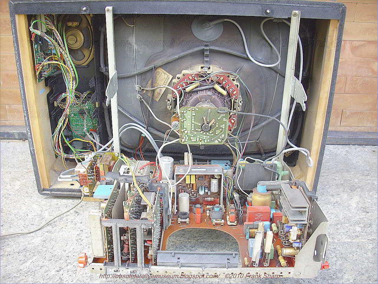