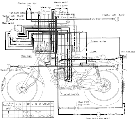
Yamaha 175 Wiring Diagram and Electrical System Schematic
The following picture shows the Yamaha 175 Wiring Diagram (CT2 and CT3 model) andElectrical System Schematic. Herein you get detail information regarding the interconnection and wiring between electrical parts and components of the motorcycle such as battery, ground, headlight, taillight, horn, rectifier, brake, flywheel magneto, etc.
| Daytime charging circuit Night time charging circuit Battery (+) circuit Ground circuit Front brake stop light Rear brake stop light Tail light Head/meter light Common circuit Headlight main circuit Headlight sub circuit Horn circuit Rectifier circuit Flasher Flasher light right Flasher light left | Green Green/Red Red Black Green/Yellow Yellow Blue Blue Brown Yellow Green Pink White Brown/White Dark Green Dark Brown |
2005 Yamaha DT125X Wiring Diagram
Generally the 2005 Yamaha DT125X electrical system consists of CDI unit, servomotor, battery, fuse, neutral switch, thermo unit, rectifier/regulator, ignition coil and main switch. You can find detail and complete 2005 Yamaha DT125X Wiring Diagram here on the last page of the service manual.
Yamaha DT250|350 Mikuni Carburetor Schematic and Diagram
The following Mikuni Carburetor Schematic and Diagram apply for Yamaha DT250 and DT350 series. The carburetor consists of following parts: pilot jet, float needle seat assembly, washer, o-ring, needle jet set bolt, needle jet washer, main jet, gasket, cover bolt, float, float lever arm, float pivot pin, float bowl gasket, float bowl, plate, float bowl screw, needle jet, throttle slide, clip, spring seat, throttle slide return spring, clip, carburetor cap, cable adjuster, etc.Find detail diagram and schematics of Yamaha DT250|350 Mikuni Carburetor here –
www.slimduck.com/dt250_dt360_carburetor.gif – source: slimduck.com.
www.slimduck.com/dt250_dt360_carburetor.gif – source: slimduck.com.
Yamaha TDM850 (1996 )Wiring Diagram and Electrical System
The Yamaha TDM850 is a Dual Sports or Adventure Sports motorcycle produced by Yamaha Motor Company of Japan, that first came out in 1991. The following wiring diagram andelectrical system troubleshooting manual actually part of 1996 Yamaha TDM850 service manual. Herein you will find detail information regardingelectrical system troubleshooting guideline and wiring diagram harness schematic of TDM850 which covers discussion on electrical components, switch inspection , ignition systemcircuit diagram and troubleshooting, electric starter system, starter motor, charging system, lighting system check, signal system wiring diagram, throttle position sensor self diagnosis.The 1996 TDM850 electrical components consists of igniter unit, starting circuit cut-off relay, rectifier/regulator, main switch, thermo switch, thermo unit, flasher relay, starter relay, fuse box, battery, rear brake switch, sidestand switch, neutral switch, and ignition coil.
Find more info about 1996 Yamaha TDM850 Wiring Diagram and Electrical System here
Yamaha Vino 125S Wiring Diagram
The following electrical system schematic shows the Yamaha Vino 125S Wiring Diagram. The electrical system consists of battery, CDI unit, carburetor heater, sidestand switch, horn, rectifier/regulator, ignition coil, rear brake light switch, starter relay, etc.
1 Main switch 2 C.D.I. magneto 3 Rectifier/Regulator 4 Battery 5 Main fuse 6 Battery (+) lead 7 Battery (-) lead 8 Wire lead 9 Starter relay 10 Starter motor 11 C.D.I. unit 12 Ignition coil 13 Auto choke unit 14 Front brake light switch 15 Rear brake light switch 16 Start switch 17 Engine stop switch 18 Starting circuit cut-off relay 19 Sidestand switch 20 Horn 21 Horn switch 22 Turn signal switch 23 Turn signal relay 24 Speedometer light 25 Tail/brake light 26 Dimmer switch 27 High beam indicator light 28 Turn signal indicator light 29 Fuel lever meter 30 Fuel sender 31 Headlight 32 Front turn signal light (left) 33 Front turn signal light (right) 34 Rear turn signal light (left) 35 Rear turn signal light (right) 36 Thermo switch 37 Carburetor heater Wiring Color Code B _ Black G _ Green L _ Blue P _ Pink R _ Red W _ White Y _ Yellow Br _ Brown Sb _ Sky blue Or _ Orange Ch _ Chocolate Dg _ Dark green B/W _ Black/White B/R _ Black/Red G/Y _ Green/Yellow G/W _ Green/White L/Y _ Blue/Yellow L/W _ Blue/White W/R _ White/Red R/W _ Red/White W/L _ White/Blue Y/R _ Yellow/Red Br/W _ Brown/White |


Electronic Engineering Project For Technical Study: Yamaha Wiring System >>>>> Download Now
BalasPadam>>>>> Download Full
Electronic Engineering Project For Technical Study: Yamaha Wiring System >>>>> Download LINK
>>>>> Download Now
Electronic Engineering Project For Technical Study: Yamaha Wiring System >>>>> Download Full
>>>>> Download LINK