Free Electronic/electric Circuit diagram for many electronic project, electrical project and electromachanical.
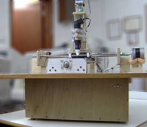
Oreginal CNC Machine
The worst bit of doing electronic projects for me is the drilling of all the holes in the PCB. Even with just a few chips, I'm soon running into hundreds of holes. I have a drill stand and miniature electric drill which helps but still it's a long and boring process. Most projects can't justify the cost of having a board made professionally either.
A little while ago, my old trusty Epson Stylus Color (sic) decided to block up its black printhead. I tried unblocking it with special cleaning fluid but some nozzles remainded resolutely gummed up or even damaged. Since it was so old and the printheads were fixed, repairing it really wasn't an option. Time to throw it away and buy a new one. I couldn't just junk it without stripping it of useful parts though. I had seen other web sites where people had built their own CNC drilling machines (Computer Numerical Control) and an old printer contains stepper motors and precisely machined stainless steel rods. The Stylus Color was no exception. I salvaged two unipolar stepper motors, the main circuit board, the button panel and the carriage together with the printhead assembly.
I had never used stepper motors before so I did some research into how to control them. The unipolar ones are easy. You just need four output lines and a set of line drivers. So that was four output lines for each of the X, Y and Z axes plus an extra one to control the miniature drill power supply. Ideally I wanted some feedback sensors too so I would need at least one input line for each of the axes. Now it just so happens that I had a computer I/O board in stock thanks to a wonderful parcel of assorted components from my friend Aaron in Texas (now Tucson) - the National Instruments PC-DIO-24. Sure it's an old ISA bus card but it could be configured to provide sixteen lines of output and eight lines of input and there was a driver for Linux.
The Circuit Design
It was time to design the electronics and test the existing hardware.So here are the initial designs:
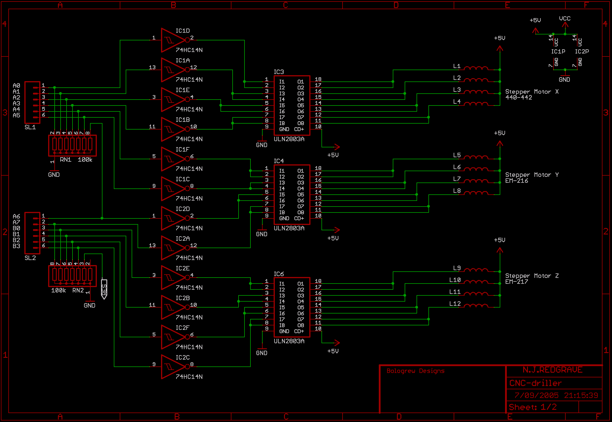
They are shrunk down but if you save the images you will get all the detail.
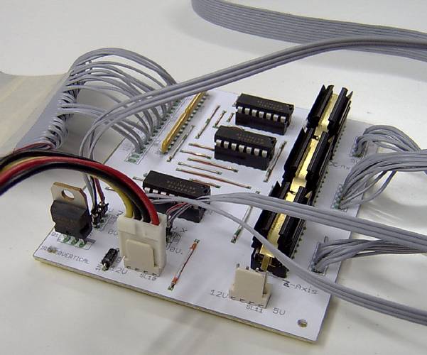
The first page handles the three stepper motors. The resistor arrays are there to pull down the CMOS inputs to prevent them from floating. The 74HC14N is an inverting buffer with Schmitt trigger inputs that clean up the signals from the I/O card. The ULN2803A is an inverting open collector Darlington line driver. The inversion undoes the inversion done by the 74HC14N. The inputs and outputs are doubled up to provide a maximum of 1A per motor coil. Theoretically, only two motor coils should be energised at any one time giving a total load of 2A per chip. The ULN2803A chips are therefore fitted with heatsinks.
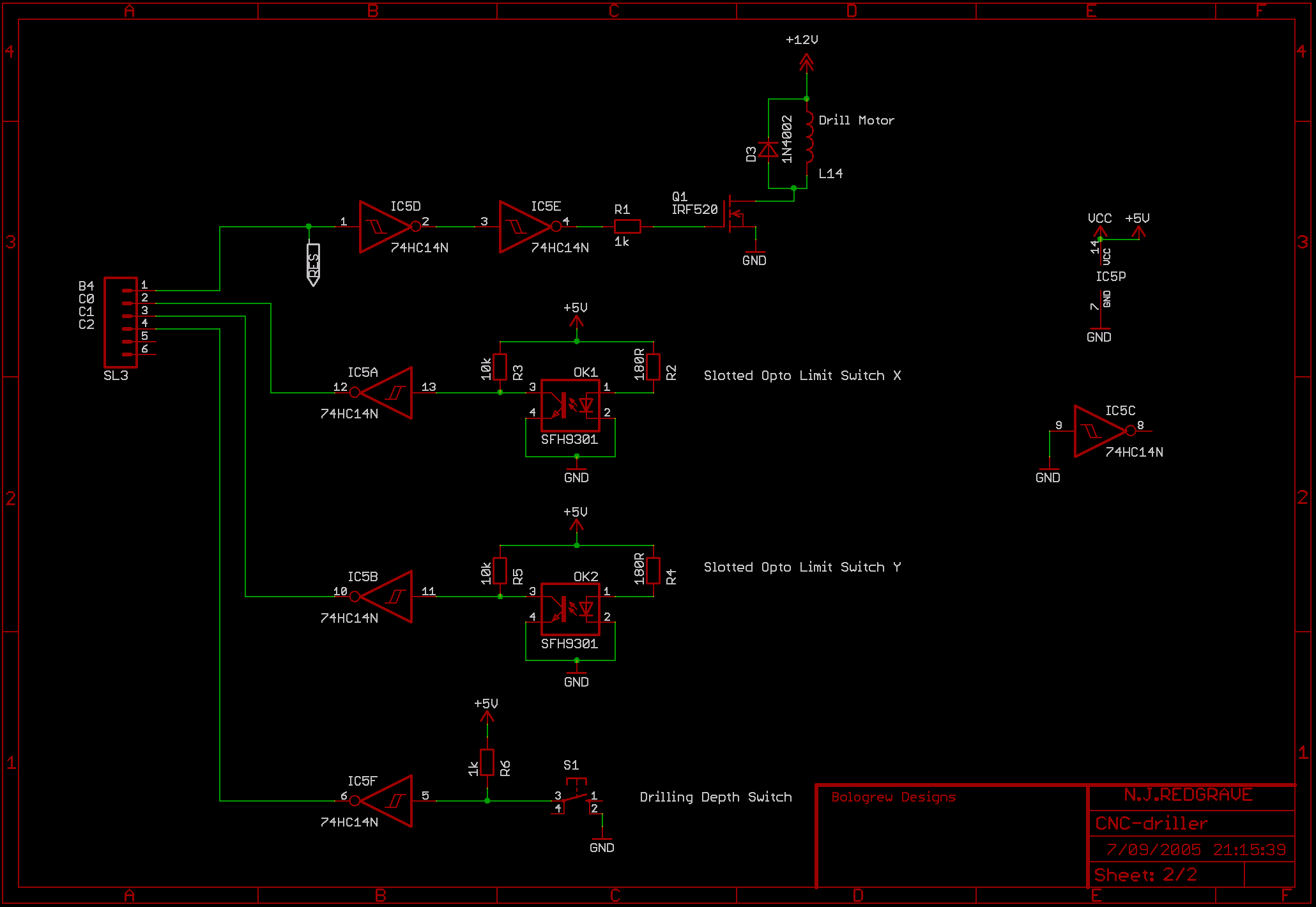
The second page handles the miniature drill motor control and the three input sensors. The drill motor control passes through two gates of a 74HC14N which cleans up the signal and undoes the inversion. That signal then connects to the gate of the IRF520 - an N-channel Power MOS transistor. It can handle a load of 10A with 100V which is a bit of an overkill but I had it in stock. The diode across the miniature drill coil prevents the back EMF from damaging the transistor.
That brings us to the input sensors. The sensors for the X and Y axes are slotted opto switches that I salvaged from a broken video recorder. All they are is an LED separated by a gap from a photo-transistor. Normally the infra-red light from the LED falls on the transistor and makes it conduct pulling the output low but when the beam is interrupted, the transistor stops conducting and the output goes high. This output is fed into a gate of a 74HC14N which cleans it up and inverts it. Lastly, the sensor for the Z axis drill depth is simply a sub-miniature push button switch salvaged from the Stylus Color button panel. The signal is high until the button is pressed pulling it low. As before, the output is cleaned up and inverted by the 74HC14N.
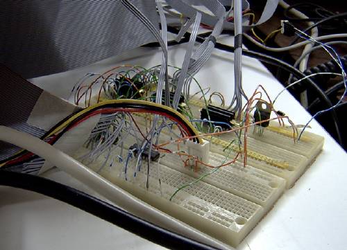
It's not pretty but it works - here is a picture of the circuitry wired up on a couple of breadboards:
The Computer
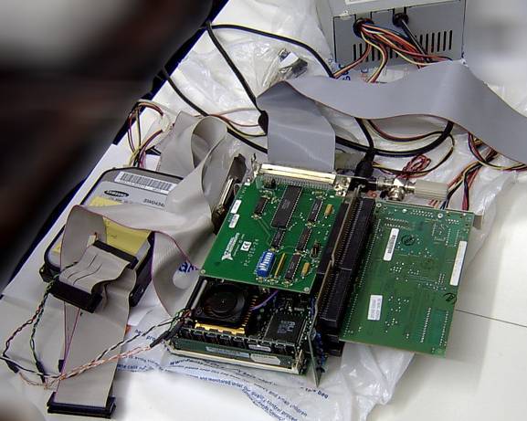
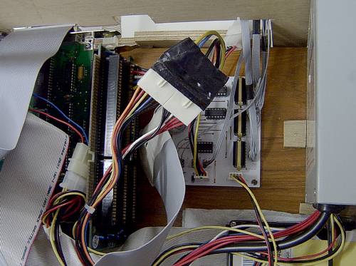
The computer powering this contraption was given to me by my ex-boss. It's a powerhouse - a 100MHz 486 with 64MB of memory. It does have onboard graphics though. So it's basically an embedded CPU board with an ISA connector that can be plugged into a passive bus. The passive bus in this case coming from an old Viglen Genie which were very neat desktop machines. For software installation, I hooked up a floppy drive and a CDROM drive to this board but they weren't going to be there in the final design. I also added an SMC-Ultra Ethernet card.Here is a picture of the lash-up showing the PC-DIO-24 on top of the CPU board and the Ethernet card to the right:
I tried a few Linux distributions on this system but ended up using Damn Small Linux. It's a live CD-style distribution but it can be installed onto a hard disk. It's not the world's fastest machine but it still has enough power to run the X Window System. It is also configured to do NFS file sharing and can be remotely accessed/controlled with SSH. It's currently running the 2.4.29 kernel. Control of the PC-DIO-24 is thanks to the Comedi drivers. I discovered that this PC-DIO-24 had been a bit too "pre-enjoyed" and three of the I/O lines had been fried. There were sufficient alternate lines to work around that but I decided to replace the 82C55 which wasn't terribly expensive. There is no protection on the 82C55's I/O lines so the use of a buffer in my schematic was a good precaution.
The Motors
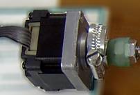
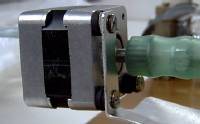
I wasn't able to dig up much information on the two motors from my Stylus Color. I decided to use the paper roller feed motor for the Y axis:What little information I could find seemed to indicate that this was a 3.6 degree per step motor with a resistance of 11 Ohms per coil.
I found a little more information about the printhead motor that I decided to use for the Z axis:
This one has a step size of 1.8 degrees, a coil resistance of 10 Ohms, a supply voltage of 3.0 to 10.0 Volts, a current per phase of 0.4 to 1.2 Amps and a continuous holding torque of 14.8 Ncm.
I did have a couple more stepper motors in stock that I salvaged from old DEC 8" floppy drives but my tests showed them to be rather weak, particularly considering that they would have to move the X axis which would also have the Z axis mounted on top. Since I had no experience with stepper motors and little real torque information on the current motors, I decided to wait until later to figure out what motor I would need for the X axis.
Time to think about the mechanical design...
Drillcon 100 - The Mechanical Design
I'm no mechanical engineer and I was on a very tight budget. I wanted to buy as little stuff as possible while still maximising my chances of making this project work. Certain design decisions were therefore going to be based on what materials I already had in stock. The drive mechanism I had decided on was simply a threaded rod held in bearings with a captive nut in the middle.
Several years ago I replaced the bearings in my original inline skates. I didn't throw the old ones away in case they came in handy one day. That day had come. They were standard 608 bearings with an inner diameter of 8 mm. That fixed the size of the threaded rod to 8 mm. I did have a choice of material though and I thought stainless steel threaded rod would be stronger and stiffer than brass. I would need some lock-nuts to hold the threaded rod to the bearings and some regular nuts to move along the rod.
I made some sketches on paper but I really needed a better way of drawing the mechanism. The answer to this was the QCad computer aided drafting program. Even better, the code is open source so all I needed to do was to download it and build it. I spent a little while reading the manual so that I had sufficient working knowledge to use the program.
I had a chipboard with wood veneer sheet that would do for the baseboard. I had well-seasoned marine ply that would make good mounting brackets and I had soft pine batten for miscellaneous mounting duties.
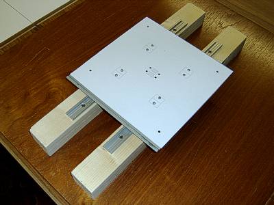
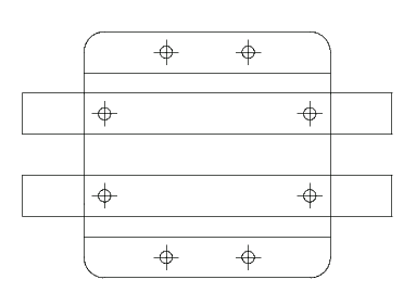
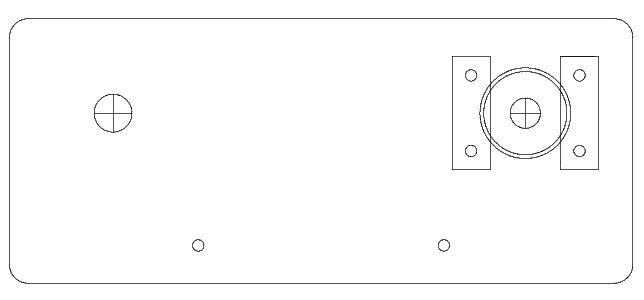
I could cut a square steel plate for the Y axis moveable bed from the case of the afore-mentioned Viglen Genie. I wanted it to be 20.0 by 20.0 cm because that would give the drill a reach of 10.0 cm on either side of the midpoint. Then the question of how to support this plate arose. I looked at smooth sliding rods but I couldn't come up with something cheap enough or something I thought I could get to work. Then I found the "DryLin N Low Profile Linear Guide" on the RS Components web site. The bottom of the range version is a 30.0 cm long aluminium rail with mounting holes. Into this rail are inserted 2.0 cm long carriages onto which can be mounted things like plates. So I decided on two rails and four carriages. This was the most expensive piece of the project at the time but I thought it would give me maximum chance of success. The parallel rails would not only keep the plate in line but would also prevent any movement in the Z axis. With two carriages inserted into each rail, the plate should essentially be self-aligning. The other advantage of the DryLin system is in its name - they don't require any lubrication. The problem with lubricating surfaces in a project like this is that drill shavings stick to the lubricant if it's something like oil.
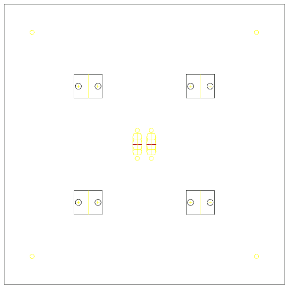
Here's a picture of the plate with the mounting positions of the four carriages, the four holes to mount a wooden plate on top of the steel one and the mounting position of the central nuts which would attach the plate to the threaded rod:
Now the question arose of how I was going to accurately make all the parts to sufficent tolerances that would allow this machine to function. If I had a drilling machine, I wouldn't need to build this in the first place. Then I realised that I did have a high precision piece of equipment that would do the job - my new Canon PIXMA iP1000 printer that I bought to replace my Stylus Color. The QCad program could print the designs with 1:1 scaling and all I had to do was cut them out and glue them to the pieces I was trying to measure and cut. The external shape of most of the pieces wouldn't be that crucial - it was the relative positions of the internal mounting points that really mattered.
I had a plan. If the Y axis didn't work then there would be no point in trying to build the Z or X axes. I ordered the DryLin Linear Guides from RS Components and the remainder of the electronic and mechanical parts from Farnell. Normally I would useMaplin but I could only get certain components from Farnell and they have a minimum order amount of £20 which I couldn't otherwise meet.
Time to start construction...
The Y Axis Construction
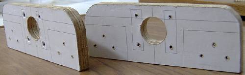
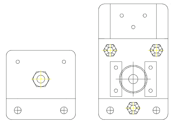
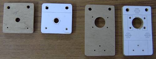
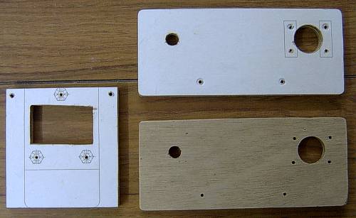
I designed an endplate to mount the bearings in with wooden battens between them on which would be mounted the linear guides.
Here's the endplate:
Here's the endplate:
Now the problem was how to make two identical plates. Simple - you don't. You make one plate. Having glued the paper design to the marine ply, I put another piece behind it and clamped it in a vice. I drilled the holes for the bearing mounts and batten mounts and then screwed the two blocks together.
Here they are:
Here they are:
Now the problem was how to make two identical plates. Simple - you don't. You make one plate. Having glued the paper design to the marine ply, I put another piece behind it and clamped it in a vice. I drilled the holes for the bearing mounts and batten mounts and then screwed the two blocks together.
Here they are:
Now I could effectively treat the two plates as one. I cut round them and then started the arduous task of first drilling out and then filing out the hole for the bearing. I got better at making the holes for the bearings as I worked on the other axes. Fortunately, the position of the bearing holes wasn't crucial for this axis because the precise positioning was going to be done by the linear guides. Once the plate was complete, all I had to do was to unscrew it and I had a pair of plates.
Like this:
Like this:
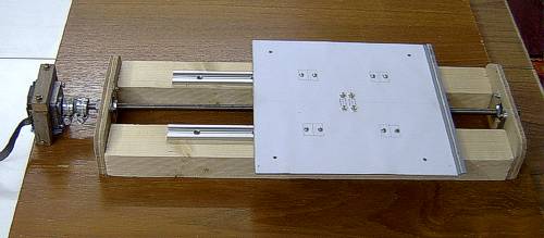
The next job was to cut out the steel plate with a jigsaw, glue the paper design to it and drill the mounting holes for the DryLin carriages, threaded rod mountings and the wooden plate mountings. Then the carriages were slid into the guides and the plate screwed into the carriages. At that point I could screw the two wooden battens to my baseboard and screw the guides onto the battens.
Like this:
Like this:
It took a fair bit of tweaking to get the plate running freely. Any slight misalignment tends to make it bind. In the end though, I could push it along the guides easily while maintaining virtually no play in the X or Z axes.
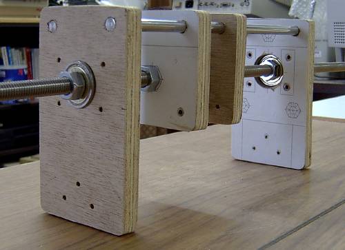
Time to put the bearings in with regular nuts and see how it all fits together:
Time to put the bearings in with regular nuts and see how it all fits together:
Now I could measure the distance from the nuts to the bottom of the plate in order to design the mounting bracket.
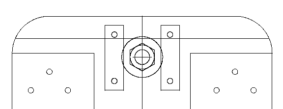
Here's what I came up with:
Here's what I came up with:
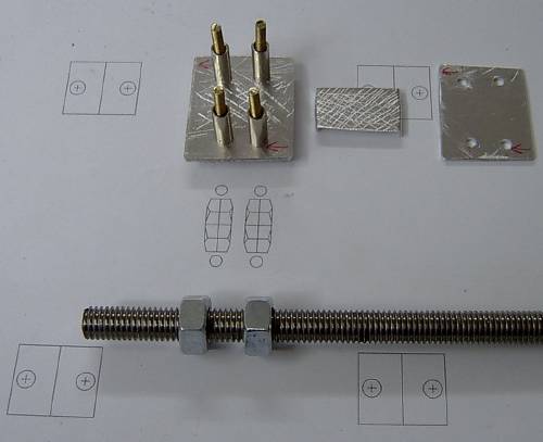
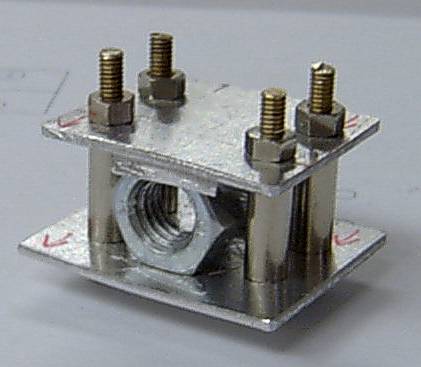
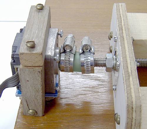
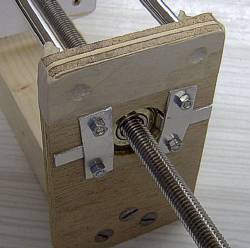
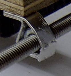
The idea is to sandwich two nuts between a set of plates. The plates are deliberately roughened so the nuts won't slip and the smaller insert plate has lips on either end to limit the travel of the nuts anyway. I used two nuts rather than one to prevent backlash. Backlash is where there is play between a nut and the threaded rod so that it is possible to reverse the direction of the rod rotation and no movement of the nut occurs until the play is taken up. With two nuts, they can be arranged so that the play is taken out of the system. This does increase friction though.
Here's the finished sandwich:
Here's the finished sandwich:
This is then bolted to the underside of the Y axis plate.
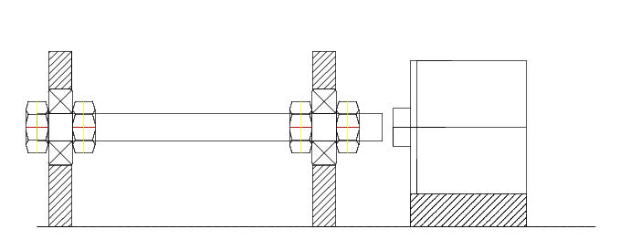
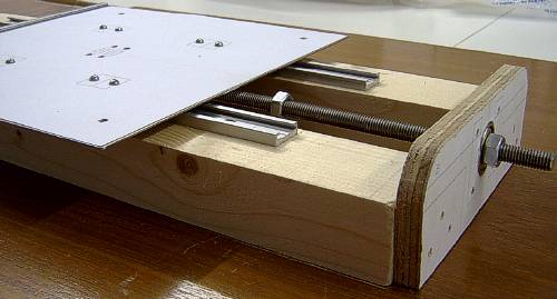
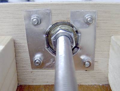
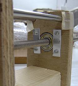
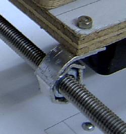
Now with the threaded rod fed through the sandwich, the end plates can be aligned and screwed to the battens. The bearings are locked into position with thin aluminium plates:
Now with the threaded rod fed through the sandwich, the end plates can be aligned and screwed to the battens. The bearings are locked into position with thin aluminium plates:
The inner bearing plates weren't too pretty since the bearings are thinner than the marine ply they are mounted in. I improved the mounting method for later axes:
The nuts at this stage were still regular ones. Once I tightened them up, I found I couldn't turn the threaded rod easily. I had enough misalignment to make the rod bind in the front bearing. I realised that the threaded rod only had to held tightly in the rear bearing since the plate itself was fixed to sliding in the linear guides. So I filed out the front bearing housing and allowed it much more freedom to move. That loosened the mechanism up sufficently so that I could now easily turn the threaded rod.
With the mechanism almost complete, I replaced the regular nuts with lock-nuts - one either side of each bearing. I also used spray polish containing silicone on the threaded rod to lubricate it. The silicone makes it more slippery while being a dry lubricant that won't make dust and drill shavings stick to it too much.
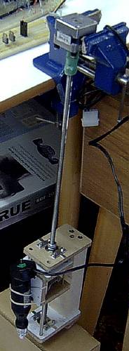
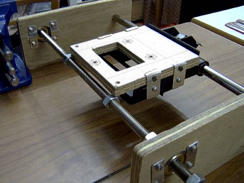
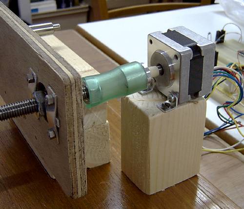
Time to do some tests. I connected the Y axis stepper motor to the threaded rod with a piece of plastic hosepipe. It's strong enough to transmit the power while being flexible enough to allow some misalignment of the shafts. I clamped my vernier ruler to the plate and used the test program to rotate the shaft 1000 steps at a time while I noted the distance moved.
Here's the setup:
With the mechanism almost complete, I replaced the regular nuts with lock-nuts - one either side of each bearing. I also used spray polish containing silicone on the threaded rod to lubricate it. The silicone makes it more slippery while being a dry lubricant that won't make dust and drill shavings stick to it too much.
Time to do some tests. I connected the Y axis stepper motor to the threaded rod with a piece of plastic hosepipe. It's strong enough to transmit the power while being flexible enough to allow some misalignment of the shafts. I clamped my vernier ruler to the plate and used the test program to rotate the shaft 1000 steps at a time while I noted the distance moved.
Here's the setup:
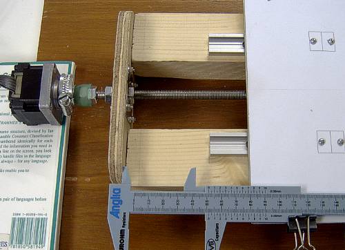
I should note at this point that the test program was written to generate half steps. As the name suggests, this halves the angle of a normal step by periodically energising two motor coils so the shaft is balanced between two normal step positions. So where I talk about steps, I'm usually talking about half steps.
Anyway, after 16000 steps, the plate had moved 103.85 mm. That's roughly 6.5 thousandths of a millimetre per step or 154 steps per millimetre! Not too shabby at all. It's not fast but it's better to be precise and accurate.
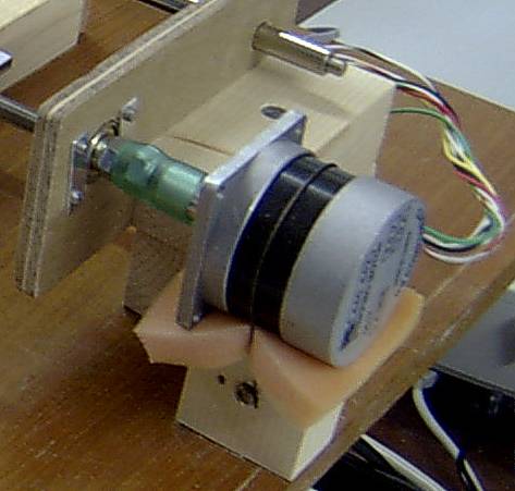
The final job was to build a mounting bracket for the stepper motor. Although I used two Jubilee clips to connect the motor to the threaded rod, the one connecting the hose to the rod turned out to be superfluous. The bracket isn't very pretty but it's easy enough to remove it should I need to fit a more powerful motor, say, for doing routing as well as drilling. I'm not sure this motor is really powerful enough for routing but I haven't actually tried it yet.
The mounted motor:
Anyway, after 16000 steps, the plate had moved 103.85 mm. That's roughly 6.5 thousandths of a millimetre per step or 154 steps per millimetre! Not too shabby at all. It's not fast but it's better to be precise and accurate.
The final job was to build a mounting bracket for the stepper motor. Although I used two Jubilee clips to connect the motor to the threaded rod, the one connecting the hose to the rod turned out to be superfluous. The bracket isn't very pretty but it's easy enough to remove it should I need to fit a more powerful motor, say, for doing routing as well as drilling. I'm not sure this motor is really powerful enough for routing but I haven't actually tried it yet.
The mounted motor:
So here is the finished Y axis:
With this success under my belt, it was time to move on to the next axis - the Z axis.
The Z Axis Construction
I now had a bit of a problem. I had blown my budget on the DryLin linear guides on the Y axis. Those same guides would make a very good Z axis but I couldn't really afford them. However, from the same old DEC floppy drive that I mentioned earlier, I had also salvaged some stainless steel rods. They would make good sliding guides. I couldn't afford any linear bearings either but I had noticed that when I filed the marine ply, it became very smooth but still very hard. Perhaps I could do without proper linear bearings? So I came up with a design with two fixed end brackets containing bearings and two sliding plates joined together by a front plate. The miniature drill would be bolted to the front plate using aluminium straps.
Here are the designs:
As before, I could bolt the marine ply together to make two brackets for the price of one. However, since the stainless steel rods had to pass through all four pieces of wood, both pairs of brackets had to be bolted together as well in order to get the alignment right.
Here are the brackets:
Time to fit the bearings, the stainless steel rods and see how it hangs together:
Now the batten backbone is attached and the frontplate for the inner brackets:
No matter how careful you are, once you attach the frontplate, it will twist the inner brackets and make it difficult to slide the mechanism. At this point I coated the inside of the inner bracket holes with floor polish containing silicone to make them nice and slippery.
Now I fitted the bearings using a better method than that of the Y axis:
Now I fitted the bearings using a better method than that of the Y axis:
To sort out the twisting of the inner brackets, I now fitted tensioning bars made out of 8BA threaded brass rod. It turned out that I had to pull one side in and push the other side out the make it square again. Once again, it slid freely along the rods.
In order to make the inner brackets move along the threaded rod, I needed to fit some captive nuts. For the same reason as the Y axis, two were needed to avoid any backlash. I made two brackets out of aluminium and trapped the nuts between them and the wooden bracket.
Here's the combined result:

Moment of truth time. I lashed my miniature drill to the frontplate and attached the second Stylus Color motor to the threaded rod which hadn't been cut to the right length yet:
In order to make the inner brackets move along the threaded rod, I needed to fit some captive nuts. For the same reason as the Y axis, two were needed to avoid any backlash. I made two brackets out of aluminium and trapped the nuts between them and the wooden bracket.
Here's the combined result:
Moment of truth time. I lashed my miniature drill to the frontplate and attached the second Stylus Color motor to the threaded rod which hadn't been cut to the right length yet:
Yes, it had no problem raising and lowering the mechanism. It was even slower than the Y axis though due to the higher resolution of the motor.
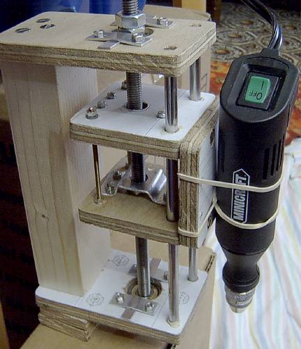
Now I replaced the regular nuts with lock-nuts, cut the threaded rod to the right length, fitted aluminium straps to the front plate for the drill mounting and made a bracket to hold the stepper motor above the threaded rod. As before, I coupled the motor to the shaft with hosepipe.
So here is the finished Z axis:
Phew! Well let's press on with the final axis..
The X Axis Construction
Here's the platform design:

Here's the side bracket design:
Once again I made both side brackets at the same time by bolting them together.
Here are the finished pieces:
Here are the finished pieces:
The platform is bolted to the side of the plastic carriage with aluminium plates and the Z axis was bolted to the platform while this was done to ensure alignment.
Here's the carriage before and after mounting:
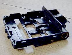
Here's the carriage before and after mounting:
Now the Z axis is unbolted, the bearings are fitted to the side plates, the Stylus Color stainless steel bar inserted and we see how it fits together:
Next I make mounting brackets to hold the captive nuts - two as before to avoid backlash. They're a nasty lash-up and I'm not proud of them. I may well return to them one day and replace them with something better and more importantly, stiffer.
Here they are:
Here they are:
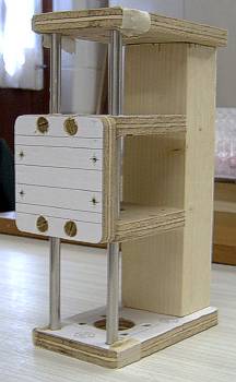
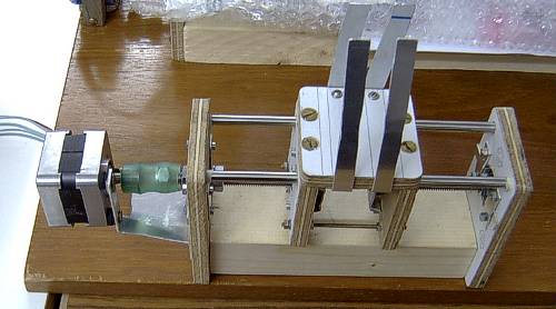
Now I reattach the Z axis and tweak everything to get it level:
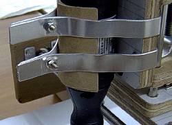
Time now to work out how high above the Y axis to mount this. To do that I need to bolt my miniature drill to the Z axis frontplate aluminium straps. I also screw the side plates to a batten so that they stay upright. It turns out that another piece of batten under either side raises the X axis by about the right amount.
Here's the result:
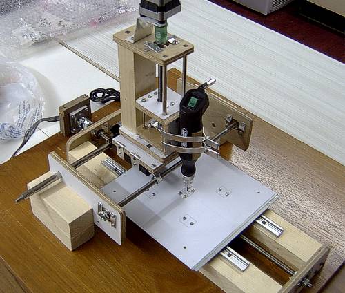
Here's the result:
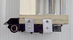
Here's a close-up of the drill mounting straps:
Now I screw the bottom battens down and then screw the top battens to the bottom battens being very careful that the X axis remains perpendicular to the Y axis. In retrospect, I probably shouldn't have mounted the blocks so far apart. Despite the thickness of the 8 mm stainless steel threaded rod, it is still surprisingly flexible. I wanted to maximise the drilling area though. It's not like it sags though. A better design would probably have a second smooth 1 cm stainless steel rod, like the Stylus Color one, attached to the front of the carriage. The threaded rod would then only be used for moving the carriage and not supporting it as well.
So I replace the regular nuts with lock-nuts and trim the threaded bar to the right length. Now comes my next mistake. I can turn the X axis threaded bar with my fingers but how much torque is that? I need to know because I haven't got a motor for this axis yet. I don't have any performance graphs for my existing motors so they can't help me much. I pored over datasheets, compared pull-in torques, holding torques, coil resistances, current per phase and make a stab at it. Below is the result:
So I replace the regular nuts with lock-nuts and trim the threaded bar to the right length. Now comes my next mistake. I can turn the X axis threaded bar with my fingers but how much torque is that? I need to know because I haven't got a motor for this axis yet. I don't have any performance graphs for my existing motors so they can't help me much. I pored over datasheets, compared pull-in torques, holding torques, coil resistances, current per phase and make a stab at it. Below is the result:
It's not a complete disaster. This Astrosyn Size 14 Mini Hybrid Stepper Motor (MY5602) is very powerful for its size. It pulls 0.76 Amps per phase at 5 Volts too. All that current in such a small volume makes it hot - very hot. Fortunately it is rated as having a maximum temperature rise of 80 degrees centigrade. Does it do the job though? Almost. Despite its size, it can move the X axis with the Z axis bolted on top most of the time. Unfortunately, most isn't going to cut it. If the motor misses steps, the holes will get drilled in the wrong places. At least it was a cheap motor. What it did do though was provide me with a reference level of the required torque. I did err on the side of caution and the motor I bought to replace it was probably a bit of an overkill. Nevertheless, it does the job and will probably do routing as well without any trouble. It's an RS 440-442, has a step angle of 1.8 degrees and pulls a maximum of 1 Amp per coil. It doesn't get as hot as the MY5602 simply because it's much bigger.
Here is the new monster motor:
That's more like it!
I performed the same calibration procedure that I did with the Y axis and it moved 80.90 mm after 26000 steps. That's roughly 3 thousandths of a millimetre per step or 321 steps per millimetre. Makes the Y axis look a bit poor! The Z axis should have the same value as the X axis since they use the same mechanism and its motor also has 1.8 degree steps.
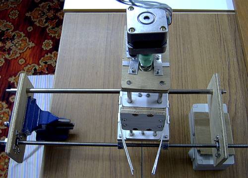
A few more odds and ends to tidy up - I soldered the sensor circuitry onto strip board and temporarily taped them onto the X and Y axes.
The sensors:
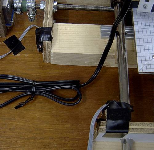
I will devise a better mounting method later. Right now it's enough to know they work and the drilling platform can work in a purely relative position mode. Once the sensors are fitted, the drilling platform will be able to know where it is in terms of absolute position. The Z depth sensor will allow it to work where the tip of the drill bit is but I'm not sure how useful that's really going to be. You can also just see the wooden plate bolted to the top of the steel plate with a grid pattern glued to the top.
Time to put the finishing touches to it.
I performed the same calibration procedure that I did with the Y axis and it moved 80.90 mm after 26000 steps. That's roughly 3 thousandths of a millimetre per step or 321 steps per millimetre. Makes the Y axis look a bit poor! The Z axis should have the same value as the X axis since they use the same mechanism and its motor also has 1.8 degree steps.
A few more odds and ends to tidy up - I soldered the sensor circuitry onto strip board and temporarily taped them onto the X and Y axes.
The sensors:
I will devise a better mounting method later. Right now it's enough to know they work and the drilling platform can work in a purely relative position mode. Once the sensors are fitted, the drilling platform will be able to know where it is in terms of absolute position. The Z depth sensor will allow it to work where the tip of the drill bit is but I'm not sure how useful that's really going to be. You can also just see the wooden plate bolted to the top of the steel plate with a grid pattern glued to the top.
Time to put the finishing touches to it.
The Case, Commissioning And The PCB
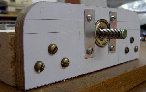
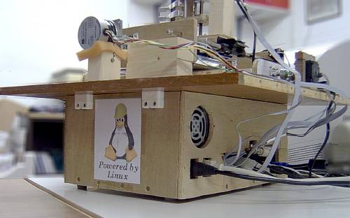
I had enough marine ply left together with the offcut of the baseboard to build a box to house the computer. I used quick release blocks to bolt the baseboard onto the top of the box. The power switch is top right on the front of the box. The two holes at the bottom left of the case are for the power and disk activity LEDs.
Here's the front:
Here's the front:
Here's the back:
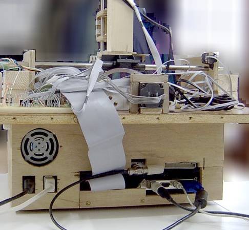
You can see the keyboard, mouse and video connections at the bottom right. Above that is the PC-DIO-24 connector. Left of that is the Ethernet connection.
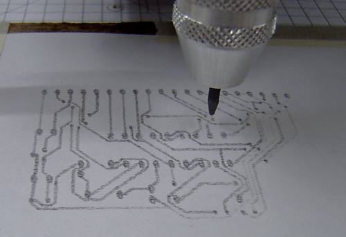
Once this new software (called the very original "drillcon") had been calibrated with the millimetres per step values that I calculated earlier, it was time to give it a drilling test. It wasn't very photogenic so there's no picture of it, but it put the holes right where they were supposed to be. Next I tried a routing test. I wasn't prepared to put a real routing bit in yet so I used a pencil lead instead.
Here's the result:
Software
In order to do something really useful with this machine, it needs to be able to understand a drilling language. Building upon the test program, I designed a more advanced piece of code that could take keyboard-entered commands as well as drill control files using a sub-set of the Excellon language. Excellon can also handle routing so it meant I only had to implement one standard. It doesn't undertand all Excellon commands but it does enough to understand the output from Eagle. It will be relatively easy to add new commands as and when required.Once this new software (called the very original "drillcon") had been calibrated with the millimetres per step values that I calculated earlier, it was time to give it a drilling test. It wasn't very photogenic so there's no picture of it, but it put the holes right where they were supposed to be. Next I tried a routing test. I wasn't prepared to put a real routing bit in yet so I used a pencil lead instead.
Here's the result:
The Circuit Board
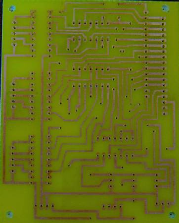
The first real drilling job for this project was to be the drilling of the printed circuit board to replace the circuitry on the breadboards. I created an alternative version of the schematics that had sockets instead of the sensors and drill coils. I layed out the board design and made the PCB.
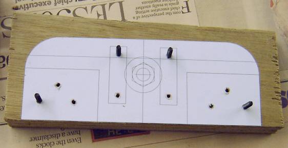
I mounted a paper printout of the board on the Y axis drill plate and taught the drillcon program where the drill bit was. I then drilled two test holes in the paper printout to verify I had mounted the printout square. By manually getting the platform to drill two holes in the PCB, I could then align the PCB and paper printout by simply putting a couple of pins through the holes. There must be a better way, but I wanted to make sure that I was going to get my drill holes in exactly the right places.
The result:
Now while it was doing the drilling, I had set up a video camera to record the operation. This board has over 200 holes of 4 different diameters. The first two were similar enough diameters to use the same 0.8 mm bit. That was about 150 holes and it took 90 minutes to drill them. I converted the video to MPEG1 and speeded it up. Once speeded up, I could see that the X axis moved up and down as it traversed. This wasn't apparent to the unaided eye. I believe the reason for this was that the lock-nuts weren't gripping the bearing tightly enough. That was a leftover from the weaker stepper motor which wasn't strong enough to move a tightened X axis. This meant that the drilling depth varied across the board. My board mounting was also too flexible and the two together resulted in some holes not being drilled all the way through. Not a complete success then, but at least it was easy to redrill the imperfect holes since there was already a hole to put the drill bit into.
The other thing I discovered was that although I was only drilling into the base of the PCB and not the copper itself (after all, I was drilling into the etched away hole positions), the 0.8 mm drill bit was completely blunt once it was finished. The Excellon control language has a facility to count the number of holes made with a particular bit and to force a tool change after a preset count. Clearly I need to implement this function in future.
That done, I glued the printout of the board top to the PCB as a poor-man's silk screen and did the bit that everyone loves - stuffing the board with components and soldering them in.
Like this:
Now I screw it to the base of computer box underneath the Ethernet card. Here's a picture of that with the Ethernet card temporarily removed to gain access:
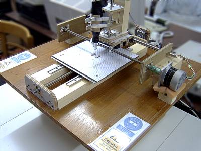


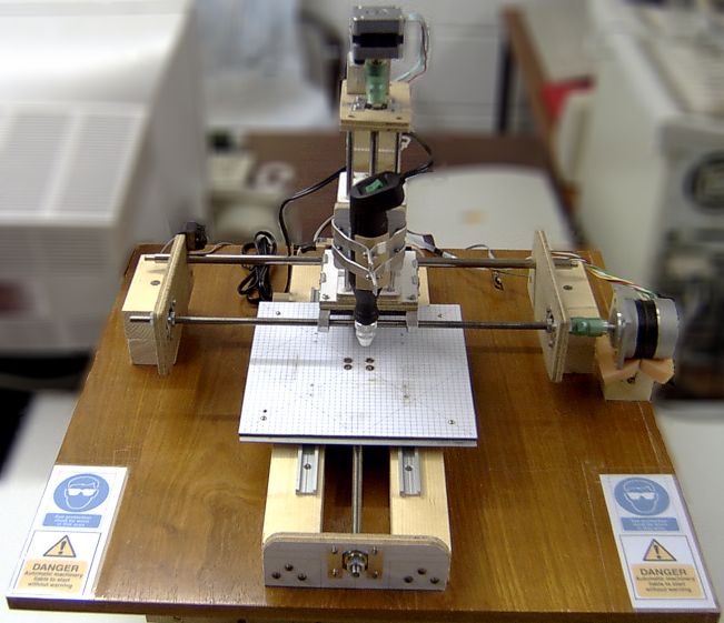
That's it. A Do It Yourself, 3 axis computer controlled drilling and routing machine - "Drillcon 100".
The Future
There are a few things on my list of things to do. The top of my list is speeding it up. This is actually harder than it sounds. The computer has to generate the coil energisation patterns for every step to get the motors to rotate. That's easy but there has to be a delay between them or else it'll send them so fast that the motors won't turn at all. So there's a "usleep" between the pattern changes. The problem is that a usleep causes a program reschedule so that even if you ask for the shortest possible delay, you always get a delay of the scheduler time slice. There are a couple of nasty hacks I could use to get round that but I'd prefer a more elegant solution. I'm currently looking at using RTAI-Linux which has a nano-scheduler with a much finer time resolution that a timer could be hooked onto. I may or may not be able to use the existing Comedi driver with that but even if I can't, the code to talk to a simple 82C55 interface card isn't difficult, even if I have to write a low level RTAI kernel module. I've done it before talking to a PCI industry pack carrier card so I'm sure I can do it again.
Once the speed is sorted out, the sensors will be a lot more useful and I can mount them permanently and incorporate their use into the drillcon program.
I still have a real routing test with copper clad board to do.
I'd like to be able to fit an appropriate pen into the drill chuck so that I can use the machine as a poor-man's silk screen printer. That's only really useful when I use surface mount components since I can then draw the component outlines on the copper side.
I also had the idea of using this machine as a 3D mapper by replacing the drill bit with a switch mechanism connected to the drilling depth circuitry. The idea then would be to make the machine perform a scan of rows and columns of X, Y coordinates and use the depth switch to tell it when the depth tip had touched the object being scanned. That would eventually produce a grid of X,Y & Z coordinates that could be imported into a 3D CAD package. I had an idea for the depth sensors using a pin with a magnetised end sitting inside a tube. At the top of the tube would be mounted a Hall effect sensor that could detect when the magnetised pin end was lifted up next to it. For a system relying on actual contact, it ought to be very low friction and very low force.
There's also the possibility of fitting a display screen of some kind to the drilling platform itself - either connected to the video port or perhaps a simpler text-only device controlled by a serial port. It's not a high priority though since the drilling machine can be controlled remotely with SSH from any machine on my local network. The network is how the Excellon control programs get to the box in the first place since it has no floppy or CDROM drives let alone anything as modern as a USB port. The drilling machine doesn't actually need a monitor, mouse or keyboard at all.
Update
I have produced a new version of the software (version 1.1) that uses full steps for the Z axis rather than half steps. That makes the drilling cycle twice as fast and actually increases the torque of the stepper motor because two coils are always energised. I've also implemented the drill bit life code so that after a preset number of holes, the drilling program stops and requests a new drill bit.


Which software is used ??? Drillcon is software ???
BalasPadamFrom where can I get this software ??
Electronic Engineering Project For Technical Study: Cnc Pcb Drill Project >>>>> Download Now
BalasPadam>>>>> Download Full
Electronic Engineering Project For Technical Study: Cnc Pcb Drill Project >>>>> Download LINK
>>>>> Download Now
Electronic Engineering Project For Technical Study: Cnc Pcb Drill Project >>>>> Download Full
>>>>> Download LINK
Electronic Engineering Project For Technical Study: Cnc Pcb Drill Project >>>>> Download Now
BalasPadam>>>>> Download Full
Electronic Engineering Project For Technical Study: Cnc Pcb Drill Project >>>>> Download LINK
>>>>> Download Now
Electronic Engineering Project For Technical Study: Cnc Pcb Drill Project >>>>> Download Full
>>>>> Download LINK Lu