WELCOME To PROJECT CIRCUIT DESIGN

Search

Isnin, Ogos 19, 2013

Cheap 12VDC to 230VAC Inverter DIY

Description
 
 
Even though today’s electrical appliances are increasingly often self-powered, especially the portable ones you carry around when camping or holidaying in summer, you do still sometimes need a source of 230 V AC - and while we’re about it, why not at a frequency close to that of the mains? As long as the power required from such a source remains relatively low - here we’ve chosen 30 VA - it’s very easy to build an inverter with simple, cheap components that many electronics hobbyists may even already have.
 
 
Though it is possible to build a more powerful circuit, the complexity caused by the very heavy currents to be handled on the low-voltage side leads to circuits that would be out of place in this summer issue. Let’s not forget, for example, that just to get a meager 1 amp at 230 VAC, the battery primary side would have to handle more than 20 ADC!. The circuit diagram of our project is easy to follow. A classic 555 timer chip, identified as IC1, is configured as an astable multivibrator at a frequency close to 100 Hz, which can be adjusted accurately by means of potentiometer P1.
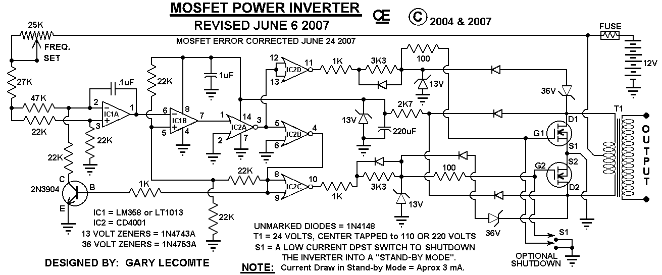
 
 
Circuit diagram:


As the mark/space ratio (duty factor) of the 555 output is a long way from being 1:1 (50%), it is used to drive a D-type flip-flop produced using a CMOS type 4013 IC. This produces perfect complementary square-wave signals (i.e. in antiphase) on its Q and Q outputs suitable for driving the output power transistors. As the output current available from the CMOS 4013 is very small, Darlington power transistors are used to arrive at the necessary output current. We have chosen MJ3001s from the now defunct Motorola (only as a semi-conductor manufacturer, of course!) which are cheap and readily available, but any equivalent power Darlington could be used.


These drive a 230 V to 2 × 9 V center-tapped transformer used ‘backwards’ to produce the 230 V output. The presence of the 230 VAC voltage is indicated by a neon light, while a VDR (voltage dependent resistor) type S10K250 or S07K250 clips off the spikes and surges that may appear at the transistor switching points. The output signal this circuit produces is approximately a square wave; only approximately, since it is somewhat distorted by passing through the transformer. Fortunately, it is suitable for the majority of electrical devices it is capable of supplying, whether they be light bulbs, small motors, or power supplies for electronic devices.
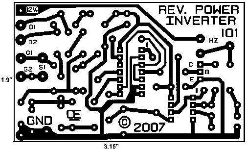
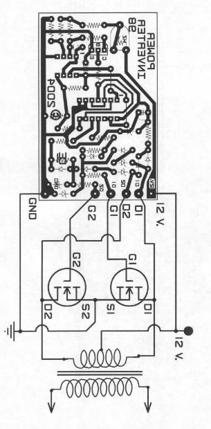
 
PCB layout:


COMPONENTS LIST
 
 
  1. R1 = 18k?
  2. R2 = 3k3
  3. R3 = 1k
  4. R4,R5 = 1k?5
  5. R6 = VDR S10K250 (or S07K250)
  6. P1 = 100 k potentiometer
  7. C1 = 330nF
  8. C2 = 1000 µF 25V
  9. T1,T2 = MJ3001
  10. IC1 = 555
  11. IC2 = 4013
  12. LA1 = neon light 230 V
  13. F1 = fuse, 5A
  14. TR1 = mains transformer, 2x9V 40VA (see text)
  15. 4 solder pins


Note that, even though the circuit is intended and designed for powering by a car battery, i.e. from 12 V, the transformer is specified with a 9 V primary. But at full power you need to allow for a voltage drop of around 3 V between the collector and emitter of the power transistors. This relatively high saturation voltage is in fact a ‘shortcoming’ common to all devices in Darlington configuration, which actually consists of two transistors in one case. We’re suggesting a PCB design to make it easy to construct this project; as the component overlay shows, the PCB only carries the low-power, low-voltage components.
 
 
The Darlington transistors should be fitted onto a finned anodized aluminum heat-sink using the standard insulating accessories of mica washers and shouldered washers, as their collectors are connected to the metal cans and would otherwise be short-circuited. An output power of 30 VA implies a current consumption of the order of 3 A from the 12 V battery at the ‘primary side’. So the wires connecting the collectors of the MJ3001s [1] T1 and T2 to the transformer primary, the emitters of T1 and T2 to the battery negative terminal, and the battery positive terminal to the transformer primary will need to have a minimum cross-sectional area of 2 mm2 so as to minimize voltage drop.


The transformer can be any 230 V to 2 × 9 V type, with an E/I iron core or toroidal, rated at around 40 VA. Properly constructed on the board shown here, the circuit should work at once, the only adjustment being to set the output to a frequency of 50 Hz with P1. You should keep in minds that the frequency stability of the 555 is fairly poor by today’s standards, so you shouldn’t rely on it to drive your radio-alarm correctly – but is such a device very useful or indeed desirable to have on holiday anyway? Watch out too for the fact that the output voltage of this inverter is just as dangerous as the mains from your domestic power sockets.


So you need to apply just the same safety rules! Also, the project should be enclosed in a sturdy ABS or diecast so no parts can be touched while in operation. The circuit should not be too difficult to adapt to other mains voltages or frequencies, for example 110 V, 115 V or 127 V, 60 Hz. The AC voltage requires a transformer with a different primary voltage (which here becomes the secondary), and the frequency, some adjusting of P1 and possibly minor changes to the values of timing components R1 and C1 on the 555.


500W Mos-Fet Power Inverter from 12VDC to 110VAC/220VAC (Build Your Self)


This circuit will provide a very stable "Square Wave" Output Voltage. Frequency of operation is determined by a pot and is normally set to 50Hz/60 Hz. Various "off the shelf" transformers can be used. Or Custom wind your own FOR BEST RESULTS. Additional MosFets can be paralleled for higher power. It is recommended to Have a "Fuse" in the Power Line and to always have a "Load connected", while power is being applied. The Fuse should be rated at 32 volts and should be aproximately 10 Amps per 100 watts of output. The Power leads must be heavy enough wire to handle this High Current Draw!


Appropriate Heat Sinks Should be used on the RFP50N06 Fets. These Fets are rated at 50 Amps and 60 Volts.
** Other types of Mosfets can be substituted if you wish.

The LT1013 offers better drive that the LM358, but its your choice.

The Power transformer must be capable of handling the chosen wattage output.
Also, Appropriate Heat Sinks are Necessary on the Mos-Fets.

Using a rebuilt Microwave transformer as shown below, it should handle about 500 watts Maximum.
It requires about 18 turn Center-Tapped on the primary.
To handle 500 watts would require using a 5 AWG wire. Pretty Heavy Stuff, but so is the current draw at that power.


How an Inverter works.


Inverter.

An inverter is used to produce an un-interrupted 220V AC or 110V AC (depending on the line voltage of the particular country) supply to the device connected as the load at the output socket.The inverter gives constant AC voltage at its output socket when the AC mains power supply is not available.

Lets look how the inverter makes this possible.To grasp the functioning of an inverter,we
should consider in the following situations.

  • When the AC mains power supply is available.
  • when the AC mains power supply is not available.


When the AC mains power supply is available.

When the AC mains supply is available,the AC mains sensor senses it and the supply goes to the Relay and battery charging section of the inverter.AC main sensor activates a relay and this relay will directly pass the AC mains supply to the output socket.The load will by driven by the line voltage in this situation.Also the line voltage is given to the battery charging section where the line voltage is converted to a DC voltage(12V DC or 24V DC usually),then regulated and battery is charged using it.There are special circuits for sensing the battery voltage and when the battery is fully charged the charging is stopped.In some inverters there will be a trickle charging circuit which keeps the battery constantly at full charge.


When the AC mains power supply is not available.

When the AC mains power supply is not available,an oscillator circuit inside the inverter produces a 50Hz MOS drive signal.This MOS drive signal will be amplified by the driver section and sent to the output section.MOSFETs or Transistors are used for the switching operation.These MOSFETs or Transistors are connected to the primary winding of the inverter transformer.When these switching devices receive the MOS drive signal from the driver circuit,they start switching between ON & OFF states at a rate of 50 Hz.This switching action of the MOSFETs or Transistors cause a 50Hz current to the primary of the inverter transformer. This results in a 220VAC or 110VAC (depending on the winding ratio of the inverter transformer) at the secondary or the inverter transformer.This secondary voltage is made available at the output socket of the inverter by a changeover relay.

Automation in an Inverter.

Inverter contains various circuits to automatically sense and tackle various situations that may occur when the inverter is running or in standby.This automaton section looks after conditions such as overload,over heat,low battery,over charge etc.Respective of the situation, the automation section may switch the battery to charging mode or switch OFF.The various conditions will be indicated to the operator by means of glowing LEDs or sounding alarms.In advanced inverters LCD screens are used to visually indicate the conditions.

 
Inverter From Manf


Inside  Inverter Set

12VDC to 230VAC POWER INVERTER DIY


CONVERT DC Voltage to AC Voltage As Power Inverters (DIY)
" Power inverter circuits are used to supply household alternating current electrical energy when only a direct current electrical energy source is available. Most commercially available power inverters provide an interface to connect to an automotive or other 12 volt DC electrical system."

A homemade power inverter electrical circuit can be constructed using two transistors, four resistors, a capacitor, an electrical transformer, electrical wire and a 12 volt battery.


 Inverter Block Diagram


Basic Circuit Diagram For Inverter

Principle of Operation


A power inverter circuit transforms direct current electrical energy into alternating current electrical energy. To do this, the circuit must make the available electrical current reverse at an interval, or oscillate.

Once the electrical energy has been converted into an oscillating form, the electrical energy can be changed by use of a transformer. A transformer can step the voltage in the circuit up or down as needed.
Fabricating the Inverter Circuit

To construct the inverter circuit, you will need two high-power PNP bipolar junction transistors, two 820Ω resistors, two 82Ω resistors, one 0.47µF polarized capacitor, one 24 volt center-tapped transformer, and a 12 volt battery. To make the electrical connections between components, you will also need electrical wire, electrical pliers, electronic (rosin core) solder and a soldering iron.

Connect the negative capacitor lead (which is marked with a "-" on the capacitor casing) jointly to one of the transformer end terminals on the center-tapped side. Connect the other transformer end terminal on the center-tapped side to the positive capacitor lead.

Connect one of the leads on the first 820Ω resistor jointly to the positive capacitor lead and to the collector lead on the first transistor. Connect the free lead on the first 820Ω resistor jointly to the first 82Ω resistor and to the base lead on the second transistor.

Connect one of the leads on the second 820Ω resistor jointly to the negative capacitor lead, and to the collector lead on the second transistor. Connect the free end of the second 820Ω resistor jointly to the second 82Ω resistor and to the base lead on the first transistor.

Connect the free leads of the two 82Ω resistors together with the emitter leads from both transistors, and attach the positive terminal of the battery to this electrical joint. Connect the negative battery terminal to the center-tap on the transformer. The voltage across the terminals on the transformer side that lacks a center-tap will be 120 volts AC.

source 


References


Sabtu, Ogos 03, 2013

Nites Rider Lights

Free Electronic/electric Circuit diagram for many electronic project, electrical project and electromachanical.


Popular Project

Another Project Blog

Project From Diff Blogger

Links

How to Find the other Websites of a Person?


DomainTools

Whois Source Logo


BetterWhois.com: Search ALL Domain Registrars

Webcams.travel - The Webcam Community - Home