CONVERT DC Voltage to AC Voltage As Power Inverters (DIY)
" Power inverter circuits are used to supply household alternating current electrical energy when only a direct current electrical energy source is available. Most commercially available power inverters provide an interface to connect to an automotive or other 12 volt DC electrical system."
A homemade power inverter electrical circuit can be constructed using two transistors, four resistors, a capacitor, an electrical transformer, electrical wire and a 12 volt battery.
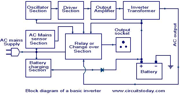
Inverter Block Diagram
Basic Circuit Diagram For Inverter
Principle of Operation
A power inverter circuit transforms direct current electrical energy into alternating current electrical energy. To do this, the circuit must make the available electrical current reverse at an interval, or oscillate.
Once the electrical energy has been converted into an oscillating form, the electrical energy can be changed by use of a transformer. A transformer can step the voltage in the circuit up or down as needed.
Fabricating the Inverter Circuit
To construct the inverter circuit, you will need two high-power PNP bipolar junction transistors, two 820Ω resistors, two 82Ω resistors, one 0.47µF polarized capacitor, one 24 volt center-tapped transformer, and a 12 volt battery. To make the electrical connections between components, you will also need electrical wire, electrical pliers, electronic (rosin core) solder and a soldering iron.
Connect the negative capacitor lead (which is marked with a "-" on the capacitor casing) jointly to one of the transformer end terminals on the center-tapped side. Connect the other transformer end terminal on the center-tapped side to the positive capacitor lead.
Connect one of the leads on the first 820Ω resistor jointly to the positive capacitor lead and to the collector lead on the first transistor. Connect the free lead on the first 820Ω resistor jointly to the first 82Ω resistor and to the base lead on the second transistor.
Connect one of the leads on the second 820Ω resistor jointly to the negative capacitor lead, and to the collector lead on the second transistor. Connect the free end of the second 820Ω resistor jointly to the second 82Ω resistor and to the base lead on the first transistor.
Connect the free leads of the two 82Ω resistors together with the emitter leads from both transistors, and attach the positive terminal of the battery to this electrical joint. Connect the negative battery terminal to the center-tap on the transformer. The voltage across the terminals on the transformer side that lacks a center-tap will be 120 volts AC.
source
References
- Lamar University: Transformer theory
- Georgia State University: Rectifiers
- Electronic Circuits Archive: 12 to 120 volt inverter circuit


Tiada ulasan:
Catat Ulasan