WELCOME To PROJECT CIRCUIT DESIGN

Search

Isnin, Ogos 19, 2013

Cheap 12VDC to 230VAC Inverter DIY

Description
 
 
Even though today’s electrical appliances are increasingly often self-powered, especially the portable ones you carry around when camping or holidaying in summer, you do still sometimes need a source of 230 V AC - and while we’re about it, why not at a frequency close to that of the mains? As long as the power required from such a source remains relatively low - here we’ve chosen 30 VA - it’s very easy to build an inverter with simple, cheap components that many electronics hobbyists may even already have.
 
 
Though it is possible to build a more powerful circuit, the complexity caused by the very heavy currents to be handled on the low-voltage side leads to circuits that would be out of place in this summer issue. Let’s not forget, for example, that just to get a meager 1 amp at 230 VAC, the battery primary side would have to handle more than 20 ADC!. The circuit diagram of our project is easy to follow. A classic 555 timer chip, identified as IC1, is configured as an astable multivibrator at a frequency close to 100 Hz, which can be adjusted accurately by means of potentiometer P1.
 
 
Circuit diagram:


As the mark/space ratio (duty factor) of the 555 output is a long way from being 1:1 (50%), it is used to drive a D-type flip-flop produced using a CMOS type 4013 IC. This produces perfect complementary square-wave signals (i.e. in antiphase) on its Q and Q outputs suitable for driving the output power transistors. As the output current available from the CMOS 4013 is very small, Darlington power transistors are used to arrive at the necessary output current. We have chosen MJ3001s from the now defunct Motorola (only as a semi-conductor manufacturer, of course!) which are cheap and readily available, but any equivalent power Darlington could be used.


These drive a 230 V to 2 × 9 V center-tapped transformer used ‘backwards’ to produce the 230 V output. The presence of the 230 VAC voltage is indicated by a neon light, while a VDR (voltage dependent resistor) type S10K250 or S07K250 clips off the spikes and surges that may appear at the transistor switching points. The output signal this circuit produces is approximately a square wave; only approximately, since it is somewhat distorted by passing through the transformer. Fortunately, it is suitable for the majority of electrical devices it is capable of supplying, whether they be light bulbs, small motors, or power supplies for electronic devices.
 
PCB layout:


COMPONENTS LIST
 
 
  1. R1 = 18k?
  2. R2 = 3k3
  3. R3 = 1k
  4. R4,R5 = 1k?5
  5. R6 = VDR S10K250 (or S07K250)
  6. P1 = 100 k potentiometer
  7. C1 = 330nF
  8. C2 = 1000 µF 25V
  9. T1,T2 = MJ3001
  10. IC1 = 555
  11. IC2 = 4013
  12. LA1 = neon light 230 V
  13. F1 = fuse, 5A
  14. TR1 = mains transformer, 2x9V 40VA (see text)
  15. 4 solder pins


Note that, even though the circuit is intended and designed for powering by a car battery, i.e. from 12 V, the transformer is specified with a 9 V primary. But at full power you need to allow for a voltage drop of around 3 V between the collector and emitter of the power transistors. This relatively high saturation voltage is in fact a ‘shortcoming’ common to all devices in Darlington configuration, which actually consists of two transistors in one case. We’re suggesting a PCB design to make it easy to construct this project; as the component overlay shows, the PCB only carries the low-power, low-voltage components.
 
 
The Darlington transistors should be fitted onto a finned anodized aluminum heat-sink using the standard insulating accessories of mica washers and shouldered washers, as their collectors are connected to the metal cans and would otherwise be short-circuited. An output power of 30 VA implies a current consumption of the order of 3 A from the 12 V battery at the ‘primary side’. So the wires connecting the collectors of the MJ3001s [1] T1 and T2 to the transformer primary, the emitters of T1 and T2 to the battery negative terminal, and the battery positive terminal to the transformer primary will need to have a minimum cross-sectional area of 2 mm2 so as to minimize voltage drop.


The transformer can be any 230 V to 2 × 9 V type, with an E/I iron core or toroidal, rated at around 40 VA. Properly constructed on the board shown here, the circuit should work at once, the only adjustment being to set the output to a frequency of 50 Hz with P1. You should keep in minds that the frequency stability of the 555 is fairly poor by today’s standards, so you shouldn’t rely on it to drive your radio-alarm correctly – but is such a device very useful or indeed desirable to have on holiday anyway? Watch out too for the fact that the output voltage of this inverter is just as dangerous as the mains from your domestic power sockets.


So you need to apply just the same safety rules! Also, the project should be enclosed in a sturdy ABS or diecast so no parts can be touched while in operation. The circuit should not be too difficult to adapt to other mains voltages or frequencies, for example 110 V, 115 V or 127 V, 60 Hz. The AC voltage requires a transformer with a different primary voltage (which here becomes the secondary), and the frequency, some adjusting of P1 and possibly minor changes to the values of timing components R1 and C1 on the 555.


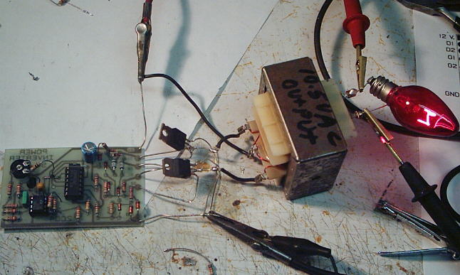
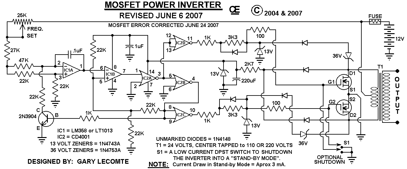
500W Mos-Fet Power Inverter from 12VDC to 110VAC/220VAC (Build Your Self)


This circuit will provide a very stable "Square Wave" Output Voltage. Frequency of operation is determined by a pot and is normally set to 50Hz/60 Hz. Various "off the shelf" transformers can be used. Or Custom wind your own FOR BEST RESULTS. Additional MosFets can be paralleled for higher power. It is recommended to Have a "Fuse" in the Power Line and to always have a "Load connected", while power is being applied. The Fuse should be rated at 32 volts and should be aproximately 10 Amps per 100 watts of output. The Power leads must be heavy enough wire to handle this High Current Draw!


Appropriate Heat Sinks Should be used on the RFP50N06 Fets. These Fets are rated at 50 Amps and 60 Volts.
** Other types of Mosfets can be substituted if you wish.

The LT1013 offers better drive that the LM358, but its your choice.

The Power transformer must be capable of handling the chosen wattage output.
Also, Appropriate Heat Sinks are Necessary on the Mos-Fets.

Using a rebuilt Microwave transformer as shown below, it should handle about 500 watts Maximum.
It requires about 18 turn Center-Tapped on the primary.
To handle 500 watts would require using a 5 AWG wire. Pretty Heavy Stuff, but so is the current draw at that power.


How an Inverter works.


Inverter.

An inverter is used to produce an un-interrupted 220V AC or 110V AC (depending on the line voltage of the particular country) supply to the device connected as the load at the output socket.The inverter gives constant AC voltage at its output socket when the AC mains power supply is not available.

Lets look how the inverter makes this possible.To grasp the functioning of an inverter,we
should consider in the following situations.

  • When the AC mains power supply is available.
  • when the AC mains power supply is not available.


When the AC mains power supply is available.

When the AC mains supply is available,the AC mains sensor senses it and the supply goes to the Relay and battery charging section of the inverter.AC main sensor activates a relay and this relay will directly pass the AC mains supply to the output socket.The load will by driven by the line voltage in this situation.Also the line voltage is given to the battery charging section where the line voltage is converted to a DC voltage(12V DC or 24V DC usually),then regulated and battery is charged using it.There are special circuits for sensing the battery voltage and when the battery is fully charged the charging is stopped.In some inverters there will be a trickle charging circuit which keeps the battery constantly at full charge.


When the AC mains power supply is not available.

When the AC mains power supply is not available,an oscillator circuit inside the inverter produces a 50Hz MOS drive signal.This MOS drive signal will be amplified by the driver section and sent to the output section.MOSFETs or Transistors are used for the switching operation.These MOSFETs or Transistors are connected to the primary winding of the inverter transformer.When these switching devices receive the MOS drive signal from the driver circuit,they start switching between ON & OFF states at a rate of 50 Hz.This switching action of the MOSFETs or Transistors cause a 50Hz current to the primary of the inverter transformer. This results in a 220VAC or 110VAC (depending on the winding ratio of the inverter transformer) at the secondary or the inverter transformer.This secondary voltage is made available at the output socket of the inverter by a changeover relay.

Automation in an Inverter.

Inverter contains various circuits to automatically sense and tackle various situations that may occur when the inverter is running or in standby.This automaton section looks after conditions such as overload,over heat,low battery,over charge etc.Respective of the situation, the automation section may switch the battery to charging mode or switch OFF.The various conditions will be indicated to the operator by means of glowing LEDs or sounding alarms.In advanced inverters LCD screens are used to visually indicate the conditions.

 
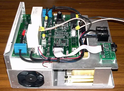
Inverter From Manf


Inside  Inverter Set

12VDC to 230VAC POWER INVERTER DIY


CONVERT DC Voltage to AC Voltage As Power Inverters (DIY)
" Power inverter circuits are used to supply household alternating current electrical energy when only a direct current electrical energy source is available. Most commercially available power inverters provide an interface to connect to an automotive or other 12 volt DC electrical system."

A homemade power inverter electrical circuit can be constructed using two transistors, four resistors, a capacitor, an electrical transformer, electrical wire and a 12 volt battery.


 Inverter Block Diagram


Basic Circuit Diagram For Inverter

Principle of Operation


A power inverter circuit transforms direct current electrical energy into alternating current electrical energy. To do this, the circuit must make the available electrical current reverse at an interval, or oscillate.

Once the electrical energy has been converted into an oscillating form, the electrical energy can be changed by use of a transformer. A transformer can step the voltage in the circuit up or down as needed.
Fabricating the Inverter Circuit

To construct the inverter circuit, you will need two high-power PNP bipolar junction transistors, two 820Ω resistors, two 82Ω resistors, one 0.47µF polarized capacitor, one 24 volt center-tapped transformer, and a 12 volt battery. To make the electrical connections between components, you will also need electrical wire, electrical pliers, electronic (rosin core) solder and a soldering iron.

Connect the negative capacitor lead (which is marked with a "-" on the capacitor casing) jointly to one of the transformer end terminals on the center-tapped side. Connect the other transformer end terminal on the center-tapped side to the positive capacitor lead.

Connect one of the leads on the first 820Ω resistor jointly to the positive capacitor lead and to the collector lead on the first transistor. Connect the free lead on the first 820Ω resistor jointly to the first 82Ω resistor and to the base lead on the second transistor.

Connect one of the leads on the second 820Ω resistor jointly to the negative capacitor lead, and to the collector lead on the second transistor. Connect the free end of the second 820Ω resistor jointly to the second 82Ω resistor and to the base lead on the first transistor.

Connect the free leads of the two 82Ω resistors together with the emitter leads from both transistors, and attach the positive terminal of the battery to this electrical joint. Connect the negative battery terminal to the center-tap on the transformer. The voltage across the terminals on the transformer side that lacks a center-tap will be 120 volts AC.

source 


References


Sabtu, Ogos 03, 2013

Nites Rider Lights

Free Electronic/electric Circuit diagram for many electronic project, electrical project and electromachanical.


Isnin, Julai 29, 2013

12VDC to 20VDC converter (Suatable for audio amplifier)


ATTENTION Keep in mind that THIS IS NOT A PROJECT FOR A BEGINNER, IT CAN BE VERY DANGEROUS IN CASE OF PROBLEMS, NEVER BRIDGE, BYPASS OR AVOID FUSES THESE WILL SAVE YOUR BACK FROM FIRE RISK.


Circuit diagrams


The limitation of car supply voltage (12V) forces to convert the voltages to higher in order to power audio amplifiers.

In fact the max audio power x speaker (with 4 ohm impedance) using 12V is (V supply +- V supply-)^2/(8*impedance) 12^2/32 = 4.5Watts per channel, that is laughable...
For powering correctly an amplifier the best is to use a symmetric supply with a high voltage differential. for example +20 - -20 = 40Volts
in fact
40^2/32 = 50 Watts per channel that is respectable.
This supply is intended for two channels with 50W max each (of course it depends on the amplifier used). Though it can be easily scaled up or the voltages changed to obtain different values.

Overview - How it works
It is a classic push-pull design , taking care to obtain best symmetry (to avoid flux walking). Keep in mind that this circuit will adsorb many amperes (around 10A) so take care to reinforce power tracks with lots of solder and use heavy wires from the battery or the voltage will drop too much at the input.
The transformer must be designed to reduce skin effect, it can be done using several insulated magnet wire single wires soldered together but conducting separately. The regulation is done both by the transformer turn ratio and varying the duty cycle. In my case i used 5+5 , 10+10 turns obtaining a step up ratio of 2 (12->24) and downregulating the voltage to 20 via duty cycle dynamic adjust performed by the PWM controller TL494.
The step-up ratio has to be a little higher to overcome diode losses, winding resistance and so on and input voltage drop due to wire resistance from battery to converter.

Transformer design
The transformer must be of correct size in order to carry the power needed, on the net there are many charts showing the power in function of frequency and core size for a given topology. My transformer size is 33.5 mm lenght, 30.0 height and 13mm width with a cross section area of 1,25cm^2, good for powers around 150W at 50khz.
The windings , especially the primary must be heavy gauged, but instead of using a single wire it is better to use
multiple wires in parallel each insulated from the other except at the ends. This will reduce resistance increase due to skin effect. The primary and secondary windings are centertapped, this means that you have to wind 5 turns, centertap and 5 windings again. The same goes for the secondary, 10 turns, centertap and 10 turns again.
The important thing is that the transformer MUST not have air gaps or the leakage inductance will throw spikes on the switches overheating them and giving a voltage higher than expected by turn ratio prediction, so if your voltage output (at fully duty cycle) is higher than Vin*N2/N1 - Vdrop diode, your transformer has gap (of course permit me saying you that you are BLIND if you miss it), and this is accompanied with a drastical efficiency reduction. Use non-gapped E cores or toroids (ferrite).

Output diodes, capacitors and filter inductor
For rectification i preferred to use shottky diodes since they have low forward voltage drop, and are incredibly fast.
I used the cheap 1N5822, the best alternative for low voltage converters (3A for current capability).
The output capacitors are 4700uF 25V, not very big, since at high frequency the voltage ripple is most due to internal cap ESR fortunately general purpose lytics have enough low esr for a small ripple (some tens of millivolts). Also at high duty cycle they are feed almost with pure DC, giving small ripple. The filter inductor on the secondary centertap furter increases the ripple and helps the regulation in asymmetrical transients

Power switch and driving
I used d2pak 70V 80A 0.004 ohms ultrafets (Fairchind semiconductor), very expensive and hard to find. In principle any fet will work, but the lower the on-resistance, the lower the on-state conduction losses, the lower the heat produced on the fets, the higher efficiency and smaller the heatsinks needed. With this fets i am able to run the fets with small heatsinks and without fan at full rated power (100W) with an efficiency of 82% and perceptible heating and with small heating at 120W (some degrees) (the core starts to saturate and the efficiency is a bit lower, around 75%)
Try to use the lowest resistance mosfet you can put your dirty hand :-) on or the efficiency will be lower than rated and you will need even a small fan. The fet driver i used is the TPS2811P, from Texas instruments, rated for 2A peak and 200ns. Is important that the gate drive is optimized for minimal inductance or the switching losses will be higher and you risk noise coupling from other sources. Personally i think that twisted pair wires (gate and ground/source) are the best to keep the inductance small. Place the gate drive resistor near the Mosfet, not near the IC.

Controller
I used the trusty TL494 PWM controller with frequency set at around 40-60 Khz adjustable with a potentiometer. I also implemented the soft start (to reduce powerup transients). The adjust potentiometer (feedback) must be set to obtain the desired voltage. The output signals is designed with two pull-up resistors on the collector of the PWM chip output transistor pulling them to ground each cycle alternatively. This signal is sent to the dual inverting MOSFET driver (TPS2811P) obtaining the correct waveform.

Power and filtering
How i said before the power tracks must be heavy gauged or you will scarify regulation (since it depends of transformer step up ratio and input voltage) and efficiency too. Don't forget to place a 10A (or 15A) fuse on the input because the car batteries can supply very high currents in case of shorts and this will save you face from a mosfet explosion in case of failture or short, remember to place a fuse also on the battery side to increase the safety (accidental shorts->fire, battery explosion, firemen, police and lawyers around). Input filtering is important, use at least 20000uF 16V in capacitors, a filter inductor would be useful too (heavygauged) but i decided to leave it..

Final considerations
This supply given me up to 85% efficiency (sometimes even 90% at some loads) with an input of 12V because i observed all these tricks to keep it functional and efficient. An o-scope would be useful, to watch the ripple and gate signals (watching for overshoots), but if you follow these guidelines you will avoid these problems.
The cross regulation is good but keep in mind that only the positive output is fully regulated, and the negative only follows it. Place a small load between the negative rail and ground (a 3mm led with a 4.7Kohm resistor) to avoid the negative rail getting lower then -20V. If the load is asymmetric you can have two cases:
-More load on positive rail-> no problems, the negative rail can go lower than -20V, but it is not a real issue for an audio amplifier.
-More load on negative rail-> voltage drop on negative rail (to ground) especially if the load is only on the negative rail.
Fortunately audio amplifiers are quite symmetrical as a load, and the output filter inductor/capacitors helps to maintain the regulation good during asymmetrical transients (Basses)

FOR FIRST TESTING USE A SMALL 12V power supply and use resistors as load monitoring switches heat and current consumption (and output) and try to determine efficiency, if it is higher then 70-75% you are set, it is enough. Adjust the frequency for best compromise between power and switching losses, skin effect and hysteresis losses

Bill Of Materials
=================
Design: 12V to 20V 100W DC-DC conv
Doc. no.: 1
Revision: 3
Author: Jonathan Filippi
Created: 29/04/05
Modified: 18/05/05

Parts
2 R1,R2 = 10
4 R3,R4,R6,R7 = 1k
1 R5 = 22k
1 R8 = 4.7k
1 R9 = 100k
2 C1,C2 = 10000uF
2 C3,C6 = 47u
1 C4 = 10u
3 C5,C7,C14 = 100n
2 C8,C9 = 4700u
1 C12 = 1n
1 C13 = 2.2u
1 U1 = TL494
1 U2 = TPS2811P
2 Q1,Q2 = FDB045AN
4 D1-D4 = 1N5822
1 D5 = 1N4148
1 FU1 = 10A
1 L1 = 10u
1 L2 = FERRITE BEAD
1 RV1 = 2.2k
1 RV2 = 24k
1 T1 = TRAN-3P3S


Credit

6VDC to 12VDC Converter


This inverter circuit can provide up to 1A of 12V power from a 6V supply. For example, you could run 12V car accessories in a 6V (British?) car. The circuit is simple, about 70% efficient and quite useful. By changing just a few components, you can also modify it for different voltages.


Circuit diagram


Parts
R1,    R4 2.2K 1/4W Resistor
R2,    R3 4.7K 1/4W Resistor
R5    1K 1/4W Resistor
R6    1.5K 1/4W Resistor
R7    33K 1/4W Resistor
R8    10K 1/4W Resistor
C1,   C2 0.1uF Ceramic Disc Capacitor
C3    470uF 25V Electrolytic Capcitor
D1    1N914 Diode
D2    1N4004 Diode
D3    12V 400mW Zener Diode
Q1,   Q2, Q4 BC547 NPN Transistor
Q3    BD679 NPN Transistor
L1     See Notes
    MISC Heatsink For Q3, Binding Posts (For Input/Output), Wire, Board

Notes
1. L1 is a custom inductor wound with about 80 turns of 0.5mm magnet wire around a toroidal core with a 40mm outside diameter.
2. Different values of D3 can be used to get different output voltages from about 0.6V to around 30V. Note that at higher voltages the circuit might not perform as well and may not produce as much current. You may also need to use a larger C3 for higher voltages and/or higher currents.
3. You can use a larger value for C3 to provide better filtering.
4. The circuit will require about 2A from the 6V supply to provide the full 800mA at 12V.

500W Inverter, 12VDC to 220VAC


Attention: This Circuit is using high voltage that is lethal. Please take appropriate precautions


This circuit you can convert the 12VDC into 220VAC. The 4047 IC is use to generate the square wave of 50hz.


Circuit diagram


How to calculate transformer rating

The basic formula is P=VI and between input output of the transformer we have Power input = Power output. 

For example if we want a 220W output at 220V then we need 1A at the output. Then at the input we must have at least 18.3A at 12V because: 12V*18.3A = 220V*1A, when P1 is 12V*18.3A and P2 is 220V*1A. 
So  if you have to wind the step up transformer 12V to 220v but input winding must be capable to bear 20A.

For this project to produce 220VAC with 500W, we find.

Output power is P2 = Output voltage x output current
        Output current = 500W/220V
                                = +- 2.272A

most importance is primary current
                           P1 = 12V x current
                      500W = 12V x current (I1)
                          I1        =  500W/12V
                                 = 41.67A

So your transformer to must be capatable to support primary current at lease 41.67A and don't forget for 2N3055 max current 15A . At lease 4 pcs for both side, total 8 pcs of 2N3055. 

try DIY


Rabu, Julai 17, 2013

Hyper fast robot line following

Free Electronic/electric Circuit diagram for many electronic project, electrical project and electromachanical.


Hyper fast robot line following 1


Hyper fast robot line following 2


Simple colour detector circuit for line tracking robots.

The given circuit is tested by myself in NCE Robotics Club ( www.facebook.com/ncerobotics ) many times with various modifications, the given circuit works very effectively.

Figure: Verified circuit diagram of color detector
The circuit can detect two different colors comparing the light reflecting capacity of those colors. As we know the light reflecting capacity of brighter color is higher than dark one, thus the different intensity of light reflected by different color surface will cause the different value of resistance in LDR ( Light Dependent Resistor ) sensor, which is converted into voltage levels by implementing LDR and a fixed resistor in voltage divider arrangement (but as fixed resistor we use preset to change the sensitivity as our desire and required level).

In above circuit, 100 ohm resistor is used to light LED1 safely with high intensity, The LDR and a preset is used as voltage divider and gives the primary output of sensor which will changes as the color of reflecting surface changes. Two 10 k ohm resistors gives the fixed ( reference) voltage to the negative terminal of comparator which is compared with the input from sensor primary output in non-inverting terminal. when the sensor primary output is below the reference voltage the sensor gives low output ( indicator is off ) and when the sensor primary output is above the reference voltage the sensor gives high output ( indicator is on). In this way the above circuit detects the colors.

For example in case of white and black color the sensor gives high output for white color and low output for black color. This logic can be altered by altering the inputs to the comparator.

By arranging these sensors in different numbers and applying as input to the micro-controller for further process we can make a line following robots easily as I have mentioned in earlier posts.

Khamis, Julai 11, 2013

Astable 555 Multivibrator


Astable 555 Multivibrator  


freq  Hzperiod Secduty cycle
Power
Ra 


Rb 


Ct 


LED1


LED2


Above in Gadget form, Astable 555 Multivibrator Gadget , for your Webpage or Google Home Page.
These are the formulae used by 555 and same is used in javascript without any change.

T1 = 0.693 (Ra + Rb) * Ct   charge time of Ct 

T2 = 0.693 (Rb * Ct)  discharge time of Ct

T = T1 + T 2    total period in seconds

F = 1 / T = 1.44 / ((Ra + (2 * Rb)) * Ct)   Frequency in Hertz

D = T 2 / T  duty cycle, multiply by 100 to get %.

Ct in farads and Ra-Rb in ohms.
The max power dissipation of 555 is 700mW so overload of more than 200mA will damage the device, connecting the battery in the reverse or wrong polarity will also damage device, ensure also Ra and Rb do not go less than 2.2K (use 4.7K minimum) as it may damage the discharge transistor at pin 7. The supply voltage can go upto 18V. For CMOS 555 like 7555 see the datasheet they are different.
the above circuit in pdf format  del00018.pdf
the cadsoft eagle source of the circuit  del00018.zip


datasheet of LM555 here pdf.
pdf links may take time to load in the browser, save file target to your disk is better.
If LEDs are not lighting up, refresh the page. Tested in Mozilla 1, Opera 5 and IE5 with javascript and images enabled.


Press the Red button below to turn on the circuit press it again to turn off. The 555 can source (LED2) or Sink (LED1) upto 200mA. It can even drive a small motor or lamp with diodes added to protect from inductive kickback.
Vary Ra, Rb and Ct with the controls given and see the change of frequency, period and duty cycle.


Ahad, Jun 30, 2013

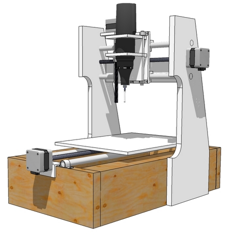
DIY Desktop CNC Machine

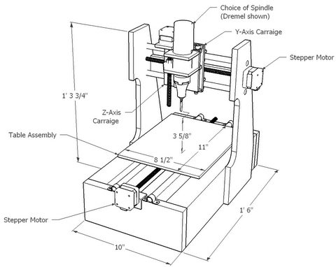
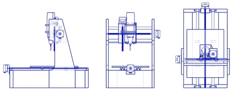
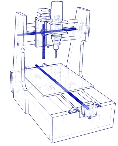
The DIY Desktop CNC Machine - automated fabrication in your home. Your personal cutting/engraving/etching/milling machine in kit form.
THE CONCEPT:
A modular, inexpensive, versatile desktop-scale CNC machine to put computer-automated machining and fabrication in the hands of creators. Whether they be hobbyists or evil scientists, small-scale manufacturers or budding inventors, the power to go from on-screen design to precision-machined product in a few mouse clicks is very exciting.
See this project Updates section for pictures and video of the working prototype.
This project will result in a finished, new, well-designed CNC machine that will then be made available in kit form at several different project entry points. From well-documented and comprehensive plans and construction manual, through electronics, motor drive and chassis kit combinations, to fully-assembeled systems, there should be a solution to fit any skill-level and/or budget.
THE PROJECT
Born out of frustration with the lack of inexpensive, straightforward and easy-to-build CNC machines I designed a DIY desktop CNC package that addresses all the objections I had with available machines. To that end the electronics are designed to be inexpensive, modular and specifically to drive the most common of stepper motors (bought or scavenged).
The machine is intended to be built by the average DIY-er, either from scratch from plans, or from a full or partial kit. Components and parts are easily available and inexpensive and the design can accommodate recycled (scavenged) parts. The electronics can be driven by several freely available software applications.
WHERE ARE WE SO FAR?
I've developed, prototyped and tested the electronics. The mechanicals have also been tested in a workhorse testbed prototype. The principals of a simple, inexpensive, easy-to-build, modular and extensible design have held up to testing. The end product design has been done in CAD and is ready to "productize". You can read more about the project history at MyDIYCNC
SO WHAT'S NEXT?
This is where you come in. The next step is to produce the DIY Desktop CNC Machine kits. So, with the help of some braniacs I know, we'll build a complete "final product" CNC machine, thoroughly soak test and troubleshoot it, and (this is the really cool part) use it to manufacture the subsequent parts for the kits.
What better test can there be for the DIY Desktop CNC Machine than to have it recreate itself?
Kickstarter will enable us to complete this design project and move it into production. For your support you'll in essence be able to pre-buy the kits at reduced pricing, along with some other goodies we'll include as our "Thank You" for making this exciting venture a reality.

Sabtu, Jun 29, 2013

SPEED TRAP


This was designed for a radio controlled car track using cars of 1/10 scale. It works by measuring the time it takes for an object to pass 2 sensors placed exactly 200mm apart. In this way the speed can be calculated in "MPH" and ms-1.


In fact 2 versions were made with the second designed exactly the same but the case was designed for indoor use.  


Designed and built by Phil Townshend 2008

The principle is simple. Take the time it takes to travel 200mm, multiply this by 5 to get the time for 1 metre then take the reciprocal.
eg: Time taken to pass 200mm = 0.1s. Then 1 metre takes 5 x 0.1 = 0.5s,
so speed = 1 / 0.5 = 2 m/s.
The speed is displayed in metres/second by default, but pressing SW2 will display the speed in MPH but at a scale speed so actually it will read 10x as much. 
The Math routines I wrote I am very pleased with. They can multiply 16bit by 8 bit numbers and are based on long division and multiplication. I wrote them myself - honest!!

The sensors used were opto-transistors and the light sources were some 1mW keyring laser pointers (I found a deal on 30 for £10 from Japan - free shipping - bargain!) The lasers and sensors were positioned such that a beams were directed across the track exactly 200mm apart. The cars would break the beams as they drove past.


Boxes were made up from 6mm MDF to protect the sensors and Laser modules and also to ensure accurate positioning.
The Lasers were mounted in wooden blocks that swivelled and could be adjusted by bolts from the sides.


CIRCUIT FUNCTIOन     

Speed Trap block diagram

Thanks to the PIC, most of the circuitry is interface control, such as buffers and drivers. The last 8 display digits are multiplexed, where only one digit is on at any one time, but all very quickly. To maintain brightness the LEDs are driven much harder than usual so protection was put in to detect if the clock ever stopped because of the PIC locking up for some random reason. In this way as soon as the display is frozen, the outputs from the shift registers is switched off. and thus in turn the display.


LED DISPLAY

he display is made up of 294 LEDs. These are divided up as follows: 
  • A fixed 5 character display to show the word "Speed"
  • Digits D to H are for the 5 digits displaying numbers and most of the alphabet letters (except for k,m,v,w,x).
  • Digits C to A are for the display of the units, either "mph" or "mps" 
  •  
  •  
CIRCUIT DIAGRAM 


Popular Project

Another Project Blog

Project From Diff Blogger

Links

How to Find the other Websites of a Person?


DomainTools

Whois Source Logo


BetterWhois.com: Search ALL Domain Registrars

Webcams.travel - The Webcam Community - Home