WELCOME To PROJECT CIRCUIT DESIGN

Search

Memaparkan catatan dengan label 555. Papar semua catatan

Khamis, September 26, 2013

555 Burglar Alarm


The circuit illustrated here is used as an Burglar alarm. LDR is kept at such a place that when thief enters our house then a shadow will fall on the LDR. A small beam of light source is also needed to supply continuous signal to LDR. For best Light source we can use Laser diode which will work for few KMs. For home use Infra Red LED’s will be good and will be tricky to thief and works with same efficiency at night.
This circuit uses a popular timer I.C which is 555. I.C 555 is connected as comparator with pin 6 connected with positive supply, the output goes high-1 when the trigger pin 2 is at lower than 1/3 level of the supply voltage. Conversely the output goes low-0 when it is above 1/3. So small change in voltage of pin 2 is enough to change the output state of pin 3 from 1 to 0 and 0 to 1. The output has only two states high and low and can not remain in any intermediate stage. It is power by 9V battery for portable use. The circuit is economic in power consumption. Pin 4,6& 8 is connected to the positive supply and pin 1 is grounded.
To detect the present robber we have used LDR and a source of light.
LDR is a special type of resistance whose value depends on the brightness of the light which is falling on it. It has a resistance of about 1 megaohms when in total darkness,but a resistance of only about 2-5 k ohms when brightly illuminated. It responds to a large part of the light spectrum.
The source of light and LDR is so adjusted with a reflector that light will directly fall on the LDR but when robber enters inside then it will block the beam of light and LDR will be under darkness.
We have made a potential divider circuit with LDR and 100 K variable resistance connected in series. Voltage is directly proportional to conductance so more voltage we will get by this divider when LDR is getting light and low voltage in darkness. Sensitiveness can be adjusted by variable resistance. Divided voltage is given to pin 2nd of 555. As soon as LDR gets dark the voltage of the pin 2 drops 1/3 of the supply voltage and pin 3 gets high and Buzzer Beeps.
For Demo we have used simple LED for LED1 may be Red or White Color


Circuit Diagram of Burglar Alarm

LED = Light Emitting Diode
LDR = Light Dependent Resistance
IC = Integrated Circuit

Components:-
  1. 9V battery with snap
  2. LDR
  3. Variable resistance 100K ohms
  4. Resistance 470 ohms
  5. LED
  6. IC 555
  7. Switch

Automatic Street Light

An introduction:
Needs no manual operation for switching ON and OFF. When there is need of light it automatically switches ON. When darkness rises to a certain value then sensor circuit gets activated and switches ON and when there is other source of light i.e. day time, the street light gets OFF. The sensitiveness of the street light can also be adjusted. In our project we have used four L.E.D for indication of bulb but for high power switching one can connect Relay (electromagnetic switch) at the output of pin 3 of I.C 555. Then it will be possible to turn ON/OFF any electrical appliances connected all the way through relay.


Principle :
This circuit uses a popular timer I.C 555. I.C 555 is connected as comparator with pin-6 connected with positive rail, the output goes high(1) when the trigger pin 2 is at lower then 1/3rd level of the supply voltage. Conversely the output goes low (0) when it is above 1/3rd level. So small change in the voltage of pin-2 is enough to change the level of output (pin-3) from 1 to 0 and 0 to 1. The output has only two states high and low and can not remain in any intermediate stage. It is powered by a 6V battery for portable use. The circuit is economic in power consumption. Pin 4, 6 and 8 is connected to the positive supply and pin 1 is grounded. To detect the present of an object we have used LDR and a source of light.

LDR is a special type of resistance whose value depends on the brightness of the light which is falling on it. It has resistance of about 1 mega ohm when in total darkness, but a resistance of only about 5k ohms when brightness illuminated. It responds to a large part of light spectrum. We have made a potential divider circuit with LDR and 100K variable resistance connected in series. We know that voltage is directly proportional to conductance so more voltage we will get from this divider when LDR is getting light and low voltage in darkness. This divided voltage is given to pin 2 of IC 555. Variable resistance is so adjusted that it crosses potential of 1/3rd in brightness and fall below 1/3rd in darkness.
Sensitiveness can be adjusted by this variable resistance. As soon as LDR gets dark the voltage of pin 2 drops 1/3rd of the supply voltage and pin 3 gets high and LED or buzzer which is connected to the output gets activated.

Circuit Diagram of Automatic Street Light

Component used :
  1. 9v Battery with strip
  2. Switch
  3. L.D.R (Light Depending Resistance)
  4. I.C NE555 with Base
  5. L.E.D (Light Emitting Diode) 3 to 6 pieces.
  6. Variable Resistance of 47 KΩ
  7. P.C.B (Printed Circuit Board of 555 or Vero board.

COMPONENTS :
  1. Battery: For 9v power supply we can use 6pcs dry cell or 6F22 9v single piece battery.
  2. Switch:  Any general purpose switch can be used. Switch is used as circuit breaker.
  3. L.D.R: (Light Depending Resistance)  It is a special type of resistance whose value depends on the brightness of light which is falling on it. It has resistance of about 1mega ohm when in total darkness, but a resistance of only about 5k ohms when brightness illuminated. It responds to a large part of light spectrum.
  4. L.E.D: (Light Emitting Diode)    A diode is a component that only allows electricity to flow one way. It can be thought as a sort of one way street for electrons. Because of this characteristic, diode are used to transform or rectify AC voltage into a DC voltage. Diodes have two connections, an anode and a cathode. The cathode is the end on the schematic with the point of the triangle pointing towards a line. In other words, the triangle points toward that cathode. The anode is, of course, the opposite end. Current flows from the anode to the cathode. Light emitting diodes, or LEDs, differ from regular diodes in that when a voltage is applied, they emit light. This light can be red (most common), green, yellow, orange, blue (not very common), or infa red. LEDs are used as indicators, transmitters, etc. Most likely, a LED will never burn out like a regular lamp will and requires many times less current. Because LEDs act like regular diodes and will form a short if connected between + and -, a current limiting resistor is used to prevent that very thing. LEDs may or may not be drawn with the circle surrounding them.
  5. Potentiometer    Resistors are one of the most common electronic components. A resistor is a device that limits, or resists current. The current limiting ability or resistance is measured in ohms, represented by the Greek symbol Omega. Variable resistors (also called potentiometers or just “pots”) are resistors that have a variable resistance. You adjust the resistance by turning a shaft. This shaft moves a wiper across the actual resistor element. By changing the amounts of resistor between the wiper connection and the connection (s) to the resistor element, you can change the resistance. You will often see the resistance of resistors written with K (kilohms) after the number value. This means that there are that many thousands of ohms. For example, 1K is 1000 ohm,2K is 2000 ohm, 3.3K is 3300 ohm, etc. You may also see the suffix M (mega ohms). This simply means million. Resistors are also rated by their power handling capability. This is the amount of heat the resistor can take before it is destroyed. The power capability is measured in W (watts) Common wattages for variable resistors are 1/8W, 1/4W, 1/2W and 1W. Anything of a higher wattage is referred to as a rheostat
  6. PCB (Printed Circuit Board)   with the help of P.C.B it is easy to assemble circuit with neat and clean end products. P.C.B is made of Bakelite with surface pasted with copper track-layout. For each components leg, hole is made. 
Connection pin is passed through the hole and is soldered.


WORKING:
When light falls on the LDR then its resistance decreases which results in increase of the voltage at pin 2 of the IC 555. IC 555 has got comparator inbuilt, which compares between the input voltage from pin2 and 1/3rd of the power supply voltage. When input falls below 1/3rd then output is set high otherwise it is set low. Since in brightness, input voltage rises so we obtain no positive voltage at output of pin 3 to drive relay or LED, besides in poor light condition we get output to energize.

Precautions:
  1. Use a Sensitive LDR. You can test it using a multimeter.
  2. I.C should not be heated too much while soldering, excess heat can destroy it. For safety and easy to replace, use of I.C base is suggested. While placing the I.C pin no 1 should be made sure at right hole.
  3. Opposite polarity of battery can destroy I.C so please check the polarity before switching ON the circuit. One should use diode in series with switch for safety since diode allows flowing current in one direction only.
  4. L.E.D glows in forward bias only so incorrect polarity of L.E.D will not glow. Out put voltage of our project is 7.3 volt therefore 4 LED in series can be easily used with out resistance.
  5. Each component should be soldered neat and clean. We should check for any dry soldered.
  6. LDR should be so adjusted that it should not get light from streetlight itself.

Khamis, Julai 11, 2013

Astable 555 Multivibrator


Astable 555 Multivibrator  


freq  Hzperiod Secduty cycle
Power
Ra 


Rb 


Ct 


LED1


LED2


Above in Gadget form, Astable 555 Multivibrator Gadget , for your Webpage or Google Home Page.
These are the formulae used by 555 and same is used in javascript without any change.

T1 = 0.693 (Ra + Rb) * Ct   charge time of Ct 

T2 = 0.693 (Rb * Ct)  discharge time of Ct

T = T1 + T 2    total period in seconds

F = 1 / T = 1.44 / ((Ra + (2 * Rb)) * Ct)   Frequency in Hertz

D = T 2 / T  duty cycle, multiply by 100 to get %.

Ct in farads and Ra-Rb in ohms.
The max power dissipation of 555 is 700mW so overload of more than 200mA will damage the device, connecting the battery in the reverse or wrong polarity will also damage device, ensure also Ra and Rb do not go less than 2.2K (use 4.7K minimum) as it may damage the discharge transistor at pin 7. The supply voltage can go upto 18V. For CMOS 555 like 7555 see the datasheet they are different.
the above circuit in pdf format  del00018.pdf
the cadsoft eagle source of the circuit  del00018.zip


datasheet of LM555 here pdf.
pdf links may take time to load in the browser, save file target to your disk is better.
If LEDs are not lighting up, refresh the page. Tested in Mozilla 1, Opera 5 and IE5 with javascript and images enabled.


Press the Red button below to turn on the circuit press it again to turn off. The 555 can source (LED2) or Sink (LED1) upto 200mA. It can even drive a small motor or lamp with diodes added to protect from inductive kickback.
Vary Ra, Rb and Ct with the controls given and see the change of frequency, period and duty cycle.


Khamis, Jun 27, 2013

Low-power inverter using LM555 Timer IC

For Electroluminescent (EL) backlights and Fluorescent tubes

Overview
This document describes a basic circuit that can be used to power high impedance, high voltage, low current devices such as EL backlights and fluorescent tubes.
This project got its genesis when I needed a simple, yet flexible inverter circuit for an EL backlight, using a 12 volt input. My specific need was to power the backlight for the wildly popular LCD-107 (specs) from All Electronics Corporation. However, this circuit is versatile enough that it should be able to power any EL strip or small (up to a few watts) fluorescent tube.
Why build instead of buy an inverter? Well, I actually bought one from one of the several surplus resale houses out there. It was apparently very poorly designed. I connected it to the backlight contacts, then to the +5V recommended, only to get a brief buzzing noise and some smoke for my trouble. I decided I could build a much more reliable, versatile inverter for just a few dollars (total cost is only about $6 for the semiconductors and transformer at your local Radio Shack), and set out to do it.
Figure 1: The el-cheapo inverter


Approach
The data sheet for this display gave me an idea of the design goals for the EL backlight:

ParameterCondition
MinTypicalMaxUnits
Voltagef=400Hz--100--V RMS
CurrentV=100V RMS, f=400Hz-- 2.9--mA RMS
Voltagef=1kHz, 60 sec max----200V RMS


It occurred to me that a simple 555 timer with a small step-up transformer should work well. The 555 timer is now ubiquitous, available on nearly any street corner via Radio Shack. For the transformer, many circuits use a filament transformer or other step-down transformer generally designed for use in a utility power supply. This wouldn't do - it would be too large and cumbersome for my needs, and besides, I didn't have a need for Big Power.

I'd had good luck in the past using 8 ohm to 1k ohm audio output transformers in "tickle stick" inverter-type applications, so I thought this might work if driven with a good oscillator.

Results

Figure 3: The prototype breadboarded version, in action
I initially setup the circuit for 400Hz operation, with the timer driving the transformer directly through a 47uF capacitor. This worked, although the display was fairly dim. After experimenting with various frequencies, I decided to add a medium-power transistor driver stage. This worked wonders! The base current and drive frequency were then tweaked to make the transistor run nice and cool, while maintaining optimum brightness on the backlight.
The final circuit parameters generate about 127 AC volts RMS, at about 2.5kHz. With these specifications, the transistor barely warms at all, and current consumption is about 110 mA at 12 volts input. The EL backlight is VERY bright!
Notice in the image to the left, the soft green-blue glow of the display. There are three LEDs (two Reds and a Green) attached to the power supply input to give an idea of relevant brightness.
Be aware that I used an old RF power transistor (a 2sc2078) I had in my junk box for Q1. However, the TIP31 should be a suitable, common replacement.
The 2sc2078 did not even require a heat sink with this design. The TIP31 is a slightly more rugged design, and might have slightly different electrical characteristics - notably, you might need to experiment a little with R3 by increasing value by a few K if the transistor gets too warm, or decrease the value by a few K if the transistor is cool but the display's too dim. See the circuit notes for more info.


Final Version
For the final version, I wanted to go from breadboard to perfboard, and make a few other changes. Because this was destined for a Media PC, I wanted to be able to power it from a standard ATX power supply. The power cord from a failed 80mm fan solved that problem; it has the requisite "in-line" Molex-style power connectors, with a tap from the 12 volt line.
I also wanted to make sure the power supply for the EL backlight could be placed with little consideration for the display location itself. A length of 18 gauge zip cord solved that.

Figure 4: The final perfboard version of the circuit, with the LCD. The el-cheapo "smokeless" inverter is also shown for reference.


Figure 5: The el-cheapo side-by-side with the 555 inverter
The completed version is comparable in size, and quite superior in performance to the original el-cheapo. Best of all, this design is easy and fun to build, using readily available components. And look ma, no smoke!


Circuit Details
Schematic diagram (click for larger version):


Parts list
ComponentDescription
U1LM555 timer IC. Do not use CMOS. Radio Shack 276-1723 or equiv.
T18 ohm to 1k ohm audio output transformer. Radio Shack 273-1380 or equiv.
Q1Medium-power NPN transistor; 2sc2078 or equiv (perhaps TIP31, Radio Shack 276-2017 or equiv.)
R11K ohm resistor
R2100K ohm resistor
R35.6K ohm resistor
C12800pF capacitor (.002uF in parallel with .001uF will do)
C2.01uF capacitor
C(bypass).1uF capacitor, in parallel with 100uF capacitor (top of schematic)
All resistors are 1/4 watt

Circuit notes:
  • It's a good idea to include the bypass capacitors. This circuit can be noisy.
  • Do not touch the output leads of the transformer. You have been warned.
  • The transformer will very quietly "sing" at 2.5 to 3.0 kHz. This is normal.
  • Experiment with the value of R3 to get the best tradeoff between brightness and transistor cool temperature.
  • A PDF of this document can be found here.

Rabu, Jun 26, 2013

Running Light LED Circuit Using LM555 + 4017 IC

4017 IC Running Light LED Circuit


The 555 Astable generates a clock for this circuit, an oscillator giving a square wave output at pin 3 which is counted by 4017 to give a running lights effect. The decade counter-divider CD4017 has 10 outputs, for every low to high transition at the clock input, rising edge, the counter advances one LED. After going one full circle the the first LED lights again and it goes on. You can vary the value of R2 100K Linear potentiometer to make LEDs run fast or slow. The frequency of oscillation of astable 555 is given as f = 1.44 / ((R4 + 2 * (R2 + R3)) * C3). The 10 outputs have 10 green LEDs. The current thru the LED is limited by R1, the current can be calculated like this (9V – 1.6V) / 1K = 7.4mA this is within 20mA which is the danger limit of the CMOS output. You want it to be bright use transistors for every output.


The cap C1 is a filter and C2 is to prevent noise at pin 5 influencing the output as it is a control voltage point. You can cascade or chain many more counters with the CO or carry out pin 12 of 4017. The pin 15 reset is kept at low for counting, on high it will reset the counter but is not used in this circuit.

Isnin, Jun 03, 2013

300W Power Inverter

300W Power Inverter

300W Power Inverter Circuit Here is a schematic 300W power inverter with 12 volt batteries as a source. This inverter is controlled by 555 timer and CD4017 decade counter. You should try to build this inverter, because it can be used to power load 300W. With the power was sufficient to illuminate a few light bulbs at night for your camping needs. This 300W power inverter is quite simple but powerful, efficient, and stable. The inverter is built using a 10V center tap transformer. A 555


Khamis, Mei 16, 2013

555 Timer Oscillator

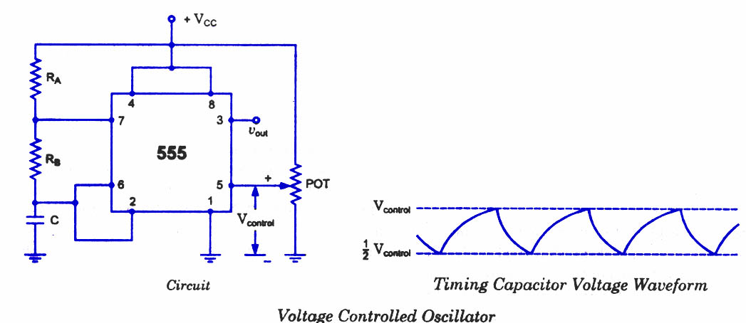
A voltage-controlled oscillator (VCO) using the timer 555 is shown in figure.

555-timer-voltage-controlled-oscillator
The circuit is sometimes called a voltage-to-frequency converter because the output frequency can be changed by changing the input voltage.
As discussed in previous blog posts, pin 5 terminal is voltage control terminal and its function is  to control the threshold and trigger levels. Normally, the control voltage is ++2/3VCC because of the internal voltage divider. However, an external voltage can be applied to this terminal directly or through a pot, as illustrated in figure, and by adjusting the pot, control voltage can be varied. Voltage across the timing capacitor is depicted in figure, which varies between +Vcontrol and ½ Vcontrol. If control voltage is increased, the capacitor takes a longer to charge and discharge; the frequency, therefore, decreases. Thus the fre­quency can be changed by changing the control volt­age. Incidentally, the control voltage may be made available through a pot, or it may be output of a transistor circuit, op-amp, or some other device.

555 Timer as an Astable Multivibrator

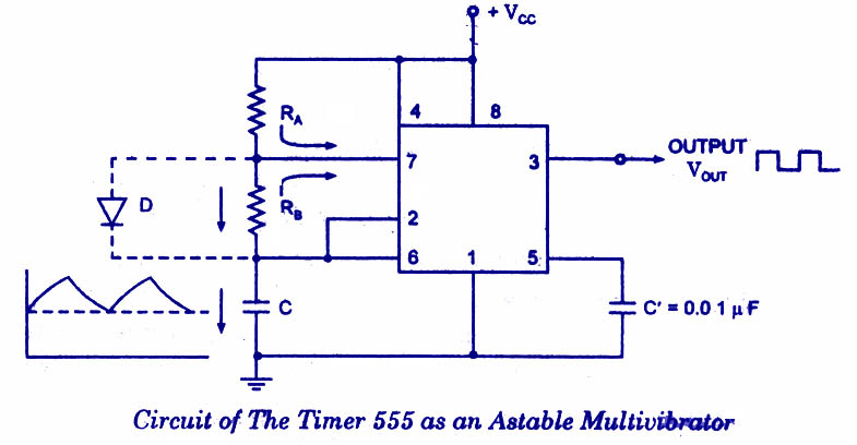
An astable multivibrator, often called a free-running multivibrator, is a rectan­gular-wave generating cir­cuit. Unlike the monostable multivibrator, this circuit does not require any ex­ternal trigger to change the state of the output, hence the name free-running. Before going to make the circuit, make sure your 555 IC is working. For that go through the article: How to test a 555 IC for working An astable multivibrator can be produced by adding resistors and a capacitor to the basic timer IC, as illustrated in figure. The timing during which the output is either high or low is determined by the externally connected two resistors and a capacitor. The details of the astable multivibrator circuit are given below.
555-Astable-Multivibrator
Take a look @ 555 Ic Pin configuration and 555 block diagram before reading further.
Pin 1 is grounded; pins 4 and 8 are shorted and then tied to supply +Vcc, output (VOUT is taken form pin 3; pin 2 and 6 are shorted and the connected to ground through capacitor C, pin 7 is connected to supply + VCC through a resistor RA; and between pin 6 and 7 a resistor RB is connected. At pin 5 either a bypass capacitor of 0.01  F is connected or modulation input is applied.

Astable Multivibrator Operation

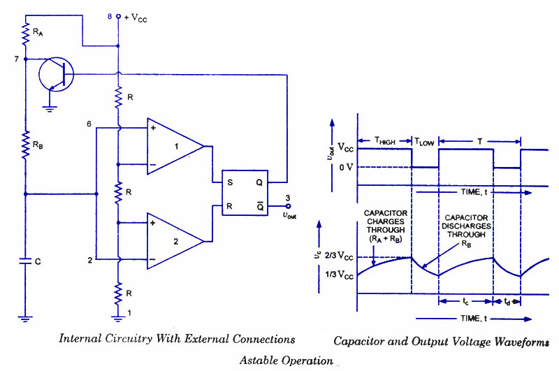
For explaining the operation of the timer 555 as an astable multivibrator, necessary internal circuitry with external connections are shown in figure.
Astable-Multivibrator-Operation
In figure, when Q is low or output VOUT is high, the discharging transistor is cut-­off and the capacitor C begins charging toward VCC through resistances RA and RB. Because of this, the charging time constant is (RA + RB) C. Eventually, the threshold voltage exceeds +2/3 VCC, the comparator 1 has a high output and triggers the flip-flop so that its Q is high and the timer output is low. With Q high, the discharge transistor saturates and pin 7 grounds so that the capacitor C discharges through resistance RB with a discharging time constant RB C. With the discharging of capacitor, trigger voltage at inverting input of comparator 2 decreases. When it drops below 1/3VCC, the output of comparator 2 goes high and this reset the flip-flop so that Q is low and the timer output is high. This proves the auto-transition in output from low to high and then to low as, illustrated in fig ures. Thus the cycle repeats.

Astable Multivibrator using 555 IC -Design method

The time during which the capacitor C charges from 1/3 VCC to 2/3 VCC is equal to the time the output is high and is given as tc or THIGH = 0.693 (RA + RB) C, which is proved below.
Voltage across the capacitor at any instant during charging period is given as,vc=VCC(1-et/RC)
The time taken by the capacitor to charge from 0 to +1/3 VCC
1/3 VCC = VCC (1-et/RC)
The time taken by the capacitor to charge from 0 to +2/3 VCC
or t2 = RC loge 3 = 1.0986 RC
So the time taken by the capacitor to charge from +1/3 VCC to +2/3 VCC
tc = (t2 – t1) =  (10986 – 0.405) RC = 0.693 RC
Substituting R = (RA + RB) in above equation we have
THIGH = tc = 0.693 (RA + RB) C
where RA and RB are in ohms and C is in farads.
The time during which the capacitor discharges from +2/3 VCC to +1/3 VCC is equal to
the time the output is low and is given as
td or  TL0W = 0.693 RB C where RB is in ohms and C is in farads The above equation is worked out as follows: Voltage across the capacitor at any instant during discharging period is given as
vc = 2/3 VCC e- td/ RBC
Substituting vc = 1/3 VCC and t = td in above equation we have
+1/3 VCC = +2/3 VCC e- td/ RBC
Or  td = 0.693 RBC
Overall period of oscillations, T = THIGH + TLOW = 0.693 (RA+ 2RB) C , The frequency of oscillations being the reciprocal of the overall period  of oscillations T is given as
f = 1/T = 1.44/ (RA+ 2RB)C
Equation indicates that the frequency of oscillation / is independent of the collector supply voltage +VCC.
Often the term duty cycle is used in conjunction with the astable multivibrator.
The duty cycle, the ratio of the time tc during which the output is high to the total time period T is given as
% duty cycle, D = tc / T * 100 = (RA + RB) / (RA + 2RB) * 100
From the above equation it is obvious that square wave (50 % duty cycle) output can not be obtained unless RA is made zero. However, there is a danger in shorting resistance RA to zero. With RA = 0 ohm, terminal 7 is directly connected to + VCC. During the discharging of capacitor through RB and transistor, an extra current will be supplied to the transistor from VCC through a short between pin 7 and +VCC. It may damage the transistor and hence the timer.
However, a symmetrical square wave can be obtained if a diode is connected across resistor RB, as illustrated in dotted lines in figure. The capacitor C charges through RA and diode D to approximately + 2/3VCC and discharges through resistor RB and terminal 7 (transistor) until the capacitor voltage drops to 1/3 VCC. Then the cycle is repeated. To obtain a square wave output, RA must be a combination of a fixed resistor R and a pot, so that the pot can be adjusted to give the exact square wave.
Although the timer 555 has been used in a wide variety of often unique applications it is very hard on its power supply lines, requiring quite a bit of current, and injecting many noise transients. This noise will often be coupled into adjacent ICs falsely triggering them. The 7555 is a CMOS version of the 555. Its quiescent current requirements are considerably lower than that of 555, and the 7555 does not contaminate the power supply lines. It is pin compatible with the 555. So this CMOS version of the 555 should be the first choice when a 555 timer IC is to be used.

Isnin, April 15, 2013

555 FUEL INJECTION SYSTEM

Free Electronic/electric Circuit diagram for many electronic project, electrical project and electromachanical.  


The Wright Brothers 1903 aircraft piston engine fuel flowed through a small metal fuel line from the high mounted tank to the engine. The fuel dripped into a flat, enclosed pan that sits on the top of the engine. The floor of the pan was hot because it sat over the hot engine cylinders. Air was drawn into the pan through the air intake, because of the action of the pistons. The combination of air being drawn over the fuel and the heat of the floor of the pan caused the gasoline to evaporate.


The fuel flow to the engine was adjusted while the aircraft was waiting on the launch rail. When the engine was running as fast and smooth as possible the aircraft was ready for launch. The pilot had a control lever which was connected to a cut-off valve to stop the engine at the end of the flight. The brothers had no throttle or engine control during the 1903 flights. The Wright "carburetor" and intake system had no moving parts. Without the moving parts, the brothers engine ran at just one speed throughout the flights of 1903.


My hangar neighbor Klaus Saviour's O-200 engine also runs with a constant speed dribble system consisting only of one small tube, poked into the throttle body, gravity feeding fuel from a header tank and using a fixed throttle opening and at a given RPM. He uses it as a back up system to his 555 integrated circuit based EFI.


Here is what a similar emergency system would look like for a two rotor Mazda p-port engine.


Airplane engines are different from car engines. Unlike car engines they have a known and repetitive load verses RPM curve using a fixed pitch prop. There are no requirements for rapid acceleration or rapid changes in load or RPM. Consequently the fuel system can be very rudimentary. In a car engine it is possible to have high RPM with low fuel flow if there is no load on the engine. You don't see that in aircraft engines with fixed pitch props. Load is probably proportional only to RPM squared when driving a prop when tip speeds are below the transonic range. At that point the load approaches very high values indeed.


The hot wire mass airflow sensor is probably the most ubiquitous way to control an automotive EFI system. It automatically compensates for humidity and intake air temperature unlike a manifold pressure sensor. You do need the e-shaft trigger but the mass air flow sensor can control the pulse width while the e-shaft triggers the injector once per revolution. Unfortunately it is not a linear device. It takes a computer to deal with it's voltage output as a function of the mass air flow through it. For that reason we are not going to use it with this system. Instead we will use manifold pressure to control a 555.

The 555 is a small and cheap integrated circuit implementing a variety of timer and multi-vibrator applications. The IC was designed and invented by Hans R. Camenzind in 1970. The original was called "The IC Time Machine". It is still in wide use, thanks to its ease of use, low price and good stability. As of 2003 one billion units are manufactured every year.


The 555 timer is one of the most popular and versatile integrated circuits ever produced. It includes 23 transistors, 2 diodes and 16 resistors on a silicon chip installed in an 8-pin mini dual-in-line package. Also available from TI are ultra-low power versions of the 555 such as the TLC555. This one works the best and it will be the one we are going to use. No other one, that I have found, works nearly as well. In essence, what the EFI computer does is gather data from its sensors and then use that data to to determine an injector pulse width. The TLC555 can do the same thing in a simple and cheap $1 chip.


The TLC555 has a pulse width modulation mode that works very well. In essence it is a complete EFI system for less than $1. One TLC555 per injector. If one fails no big deal.

This next chart from Paul Yaw shows the wider dynamic range of the more modern fuel injectors. The purple line. The delay on the lower end is the dead time.Earlier Mazda injectors had a longer dead time so it was necessary to use staged injectors. In other words one injector per rotor at low power and a two injectors per rotor at higher powers. I don't think that is now necessary for aircraft use. Also idle and low RPM with car use precise fuel control was very important to to emissions requirements.


The main sensor required is the intake manifold pressure.


The TLC555 can change the amount of fuel over a nine to one range at 6000 RPM as the pulse width varies from 1 msec to 9.5 m sec as the signal from the mass airflow sensor changes its output voltage from zero to five volts. A bonus for the TLC 555 chip is it's high output drive current of 15 ma source and 150 ma sink on pin 3. It is not your grandfather's 555 or even your dad's for that matter. That should be enough to drive the injector FET directly and it was.


I am talking about a complete TLC555 based EFI system costing less than 100 dollars while the cheapest micro computer system, the Megasquirt, is over $300 (completely assembled). Tracy Crook's dual system is over $750 and many, like the Haltech, are over $1000. Plus the TLC555 EFI is a super simple system and anybody that anybody can fix or build from scratch. No need to learn programming or guess what a proprietary EFI software program is trying to do. There is no software. Suitable carburetor's are over $1000.
Here is the skematic.


You don't need a degree in computer science or electronics to understand it or fix it. Any mechanic or electronics technician should be able to build and fix it. It is organized as three simple and reliable systems. Simple manual controls in the form of switches help diagnose the system and give flexibility of use.


The Trigger system conditions the pulse from the e-shaft position sensors and feeds it to the Injector driver. Only one trigger system is require per rotor. More than one trigger system can be implemented for redundancy as this is a true modular system with stand alone capabilities.


The Injector Driver system contains the TLC 555 and a transistor to turn the injector on and off. One or two can be used per rotor. If two are used per rotor and the engine is two rich at idle one per rotor can be turned off with the addition of two switches. Smooth running at low RPM is seldom required of an aircraft engine. Newer injectors have a wider dynamic range so smooth running is still possible with four injectors. In other words the minimum amount of fuel injected has been extended downward. We will find out when we test various injectors.


The Leaning System is used to lean the engine at cruise. One per rotor can be used to adjust the mixture on each rotor separately. You don't have to use one per rotor if you don't want to. One unit can lean all injectors. Its output is connected to pin 5 of the TLC555 to control the pulse width. It get's its input information voltage from the mass airflow sensor. We would set up the TLC 555 pulse width in an aircraft engine to be rich all the time for engine acceleration purposes. No need for an accelerator pump. Many aircraft engine carbs don't have them. Once you reach cruise you lean the mixture to as little as 18:1 for best BSFC.


There are two sensors on the e-shaft steel trigger plate 180 degrees out... one for each rotor. The angular position of the sensors control when the fuel is injected. Here are a couple of stock Mazda triggers.

Also note it is simple to adapt this system to a three or four rotor engine. Just replicate the systems as needed. This is an e-shaft trigger mounted on Mark Steitle's three rotor powered Lancair ES. The trigger wheel shown is not the right one for this system.

Test set up for magnetic trigger.

As you can see all I used is a simple bar of steel about 6 inches long 3/4 inch wide and 1/8th inch thick. This is to trigger the 555 fuel injectors. It can be rotated on the e-shaft pulley to set the injector timing anywhere. The scope is set at 5 volts per vertical division and 10 ms per horizontal division.


At 1500 RPM it is still - 30 volts which is more than enough to trigger the 555. A simple full wave bridge is used that only requires four low cost diodes.


The ideal trigger tooth is about 1/4 to 3/8 thick (wide) and comes to a sharp point. The spacing must be .050 or less. The amplitude of the trigger pulse is a very VERY strong function of the spacing. 0.010 will make a HUGE difference.


I would use a feeler gage to set it.


There will be only one trigger tooth and four mag pickups. Two for ignition (about 22 degrees BTDC) and two for fuel injection (about 90 degrees BTDC). The angular position of the pickup relative to top dead center will adjust the timing of both 555 fuel injection and ignition.


A fuel injector is nothing more than an electronically controlled valve. It is supplied with pressurized fuel by the fuel pump and it is capable of opening and closing many times per second. The amount of fuel supplied to the engine is determined by the amount of time the fuel injector stays open. This is called the pulse width. Injectors are classified into two categories.


High coil resistance (saturated) 12-16 Ohms.


Low coil resistance (peak & hold) 0.5-6 Ohms.


Saturated injectors require roughly 1-1.5 amps to open the injector. Peak & hold injectors initially needs about 4-6 amps, and once open drops to roughly 2-3 amps to keep it open. This system uses the high coil resistance injectors to keep it simple. With four injectors and a P-port engine you will need injectors capable of feeding about 75 Horses each.


Fuel Injector flow rates compiled by steve@aems.com.au


Injectors listed by max flow rate, from lowest to highest


Conversion From cc per min to lbs per hour to HP. 500cc per minute is approximately equal to 49lbs per hour which is equal to approximately 100 HP.


Common conversions

lbs/hour = cc per minute / 10.2


lbs per hour = HP / 2.04


cc per minute = lbs per hour x 10.2


cc per minute = HP x 5


HP = cc per minute / 5


HP = lbs per hour x 2.04


Note: This is a rough guide for conversions and flow rates. If you have any information that would help in increasing the quality of this data base, please send email to steve@aems.com.au.


I really like the small diameter of the RX8 injectors. They may not flow enough for a p-port engine however. Two can be mounted side by side on a 2 inch P-port intake tube.


Here is what the 250 HP p-port installation looks like.

Here is what the p-port installation looks like with the mandatory air box plenum. If you don't do this tuned intake system spit back fuel vapor and it can be a fire hazard. See UTUBPLEASE for a Youtube video of a p-port RX8 engine running on a dyno showing the spit back.
One of the problems most people are confronted with is obtaining connectors. There appears to be no standardized fuel injector connectors. Here are a couple of examples.


Here is a way around it. These are Molex female sockets used in just about every PC in the world to connect the power supply to the mother board. Electronic stores like Fry's sells them for about $1 a dozen. solder them to the wires and use a bit of heat shrink tubing. When you are ready to fly you can put a dab of red RTV in the socket to hold them in. If you grease the walls of the socket you might get lucky and have your own custom injector plugs after the red RTV hardens.


Sabtu, April 13, 2013

SPEED CHECKER FOR HIGHWAYS

Speed Checker for Highways
While driving on highways, motorists should not exceed the maximum speed limit permitted for their vehicle. However, accidents keep occurring due to speed violations since the drivers tend to ignore their speedometers. This speed checker will come handy for the highway traffic police as it will not only provide a digital display in accordance with a vehicle’s speed but also sound an alarm if the vehicle exceeds the permissible speed for thehighway. The system basically comprises two laser transmitter-LDR sensor pairs, which are installed on the highway 100 metres apart, with the transmitter and the LDR sensor of each pair on the opposite sides of the road. Theinstallation of lasers and LDRs is shown in Fig. 1. The system displays the time taken by the vehicle in crossing this 100m distance from one pair to the other with a resolution of 0.01 second, from which the speed of the vehicle can be calculated as follows:
As per the above equation, for a


speed of 40 kmph the display will read 900 (or 9 seconds), and for a speed of 60 kmph the display will read 600 (or 6
seconds). Note that the LSB of the display equals 0.01 second and each succeeding digit is ten times the preceding digit. You can similarly calculate the other readings (or time).
Circuit description
Fig. 2 shows the circuit of the speed checker. It has been esigned assuming that the maximum permissible speed for highways is either 40 kmph or 60 kmph as per the traffic rule.
The circuit is built around five NE555 timer ICs (IC1 through IC5), four CD4026 counter ICs (IC6 through IC9) and four 7-segment displays (DIS1 through DIS4). IC1 through IC3 function as monostables, with IC1 serving as count-start mono, IC2 as count-stop mono and IC3 as speed-limit detector
mono, controlled by IC1 and IC2 outputs. Bistable set-reset IC4 is also controlled
by the outputs of IC1 and IC2 and it (IC4), in turn, controls switching on/off of the 100Hz (period = 0.01 second) astable timer IC5.
The time period of timer NE555 (IC1) count-start monostable multivibrator is adjusted using preset VR1 or VR2 and capacitor C1. For 40kmph limit the time period is set for 9 seconds using preset VR1, while for 60kmph limit the time period is set for 6 seconds using preset VR2. Slide switch S1 is used to select the time period as per the speed limit (40 kmph and 60 kmph, respectively). The junction of LDR1 and resistor R1 is coupled to pin 2 of IC1.
Normally, light from the laser keeps falling on the LDR sensor continuously and thus the LDR offers a low resistance and pin 2 of IC1 is high. Whenever light falling on the LDR is interrupted by any vehicle, the LDR resistance goes high and hence pin 2 of IC1 goes low to trigger the onostable.
As a result, output pin 3 goes high for the preset period (9 or 6 seconds) and LED1 glows to indicate it. Reset pin 4 is controlled by the output of NAND generator IC5. IC5 can also be reset via diode D2 at power-on as well as when reset switch S2 is pressed. IC5 is configured as an astable multivibrator whose time period is decided by preset VR3, resistor R12 and capacitor C10. Using preset VR1, the frequency of the astable multivibrator is set as 100 Hz. The output of IC5 is fed to clock pin 1 of decade counter/7- segment decoder IC6 CD4026. gate N3 at power-on or whenever reset switch S2 is pushed. For IC2, the monostable is triggered in the same way as IC1 when the vehicle intersects the laser beam incident on LDR2 to generate a small pulse for stopping the count and for use in the speed detection. LED2 glows for the duration for which pin 3 of IC2 is high.
The outputs of IC1 and IC2 are fed to input pins 2 and 1 of NAND gate N1, respectively. When the outputs of IC1 and IC2 go high simultaneously (meaning that the vehicle has crossed the preset speed limit), output pin 3 of gate N1 goes low to trigger monostable timer IC3. The output of IC3 is used for driving piezobuzzer PZ1, which alerts the operator of speed-limit violation. Resistor R9 and capacitor C5 decide the time period for which the piezobuzzer
sounds. The output of IC1 triggers the bistable (IC4) through gate N2 at the leading edge of the count-start pulse. When pin 2 of IC4 goes low, the high output at its pin 3 enables astable clock
generator IC5. Since the count-stop pulse output of IC2 is connected to pin 6 of IC4 via diode D1, it resets clock IC CD4026 is a 5-stage Johnson decade counter and an output decoder that converts the Johnson code into a 7-segment decoded output for driving DIS1 display. The ounter advances by one count at the positive clock signal transition. The carry-out (Cout) signal from CD4026 provides one clock after every ten clock inputs to clock the succeeding decade counter in a multidecade counting chain. This is achieved by connecting pin 5 of each CD4026 to pin 1 of the next CD4026.
A high reset signal clears the deFig. 3: Power supply Fig. 4: Actual-size, single-side PCB layout for the speed checker Fig. 5: Component layout for the PCB Construction 62
cade counter to its zero count. Pressing switch S2 provides a reset signal to pin 15 of all CD4026 ICs and also IC1 and IC4. Capacitor C12 and resistor R14 generate the power-on-reset signal.
The seven decoded outputs ‘a’ through ‘g’ of CD4026s illuminate the proper segment of the 7-segment displays (DIS1 through DIS4) used for representing the decimal digits ‘0’ through ‘9.’ Resistors R16 through R19 limit the current across DIS1 through DIS4, respectively.
Fig. 3 shows the circuit of the power supply. The AC mains is stepped down by transforme X1 to deliver the secondary output of 15 volts, 500 mA. The transformer output is rectified by
a bridge rectifier comprising diodes D3 through D6, filtered by capacitor C14 and regulated by IC11 to provide regulated 12V supply. Capacitor C15 bypasses any ripple in the regulated
output. Switch S3 is used as the ‘on’/ ‘off’ switch. In mobile application of the circuit, where mains 230V AC is not available, it is advisable to use an external 12V battery. For activating the lasers used in conjunction with LDR1 and LDR2, separate batteries may be used.

Construction and working
Assemble the circuit on a PCB. An actual-size, single-side PCB layout for the speed checker is shown in Fig. 4 and its component layout in Fig. 5. Before operation, using a multimeter check whether the power supply output is correct. If yes, apply power supply to the circuit by flipping switch S3 to ‘on.’ In the circuit, use long wires for connecting the two LDRs, so that you can take them out of the PCB and install on one side of the highway,
100 metres apart. Install the two laser transmitters (such as laser torches) on the other side of the highway exactly opposite to the LDRs such that laser  light falls directly on the LDRs. Reset  the circuit by pressing switch S2, so the  display shows ‘0000.’ Using switch S1,  select the speed limit (say, 60 kmph) for  the highway. When any vehicle crosses
the first laser light, LDR1 will trigger  IC1. The output of IC1 goes high for  the time set to cross 100 metres with  the selected speed (60 kmph) and LED1  glows during for period. When the vehicle crosses the second laser light, the output of IC2 goes high and LED2
glows for this period. Piezobuzzer PZ1 sounds an alarm if the vehicle crosses the distance between the laser set-ups at more than the selected speed (lesser period than preset
period). The counter starts counting when the first laser beam is intercepted and stops when the second laser beam is intercepted. The time taken by the  vehicle to cross both the laser beams is displayed on the 7-segment display. For 60kmph speed setting, with timer frequency set at 100 Hz, if the display count is less than ‘600,’ it means that the
vehicle has crossed the speed limit (and simultaneously the buzzer sounds). Reset the circuit for monitoring the speed of the next vehicle. 

Note. This speed checker can check the speed of only one vehicle at a time.


Popular Project

Another Project Blog

Project From Diff Blogger

Links

How to Find the other Websites of a Person?


DomainTools

Whois Source Logo


BetterWhois.com: Search ALL Domain Registrars

Webcams.travel - The Webcam Community - Home