Robot Lawnmower
And today's weather will be... FINE!
Note that at the time of writing, browser support for CSS3 marquees was very limited (or non-existent). For this reason, the WebKit version has been included in this example. Therefore, if this example does not appear to be working, try viewing it in either Safari or Google Chrome.
Robotic Lawnmower
Robotic Lawnmower
- Introduction
Hi. My name is Eddie Leighton and I live in a historical small
town called Lichtenburg in South Africa. I enjoy designing and
building simple electronic projects , technical computer
programming , hobby robotics and amateur radio
(Call sign ZS6BNE since 1975). This is a snapshot of me
taken in February 2001 in my home electronics workshop
and "Ham shack".
town called Lichtenburg in South Africa. I enjoy designing and
building simple electronic projects , technical computer
programming , hobby robotics and amateur radio
(Call sign ZS6BNE since 1975). This is a snapshot of me
taken in February 2001 in my home electronics workshop
and "Ham shack".

Eddie Leighton (ZS6BNE)
- Previous robots
The first desktop robot I ever built is
shown below. This robot has an "
Umbilical Cord" which is plugged into
a printer port of any standard IBM or
compatible PC.
shown below. This robot has an "
Umbilical Cord" which is plugged into
a printer port of any standard IBM or
compatible PC.
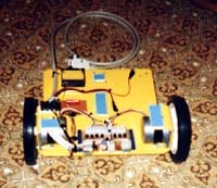
"ELeigh" the desktop robot
It used to have a 386DX40 onboard PC and an infrared sensor
mounted on a third stepper motor to allow it to "Look around"
but the Power requirement to Weight ratio was just too high
and the stepper motors battled to handle the load.
mounted on a third stepper motor to allow it to "Look around"
but the Power requirement to Weight ratio was just too high
and the stepper motors battled to handle the load.
"Eleigh" with onboard 386 and infrared detector
The coils of the two stepper motors were controlled via the
printer port by software for the desired movements of the robot.
This provided me with a very good basis for experimenting with
robotics and stepper motors in general. Power was supplied to
the coils of the stepper motors by a 6 volt Gel battery carried on
the robot. There are also facilities for sending back five signals
from the robot to the controlling PC printer port for sensor
experimentation.

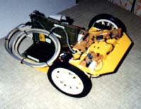
- Humble beginnings
This is where it all started. A floor full of parts shown above.
I managed to purchase two identical second hand Nissan Skyline
wiper motors and a 12 volt blower motor from a motor scrap
yard dealer in Potchefstroom not too far from my home in
Lichtenburg , Northwest Province , South Africa. The wheels
are standard 170 mm diameter lawnmower wheels obtained
from the local hardware store. Their traction is not all that
good but they made a good start for the robot lawnmower
project. The only component which I could not use for the
robot lawnmower was the dustbin lid which was too small ,
but I used it on my first desktop robot and it gave the robot a
nice "Turtle" effect. Although the MACH 2013 Robot
Lawnmower (The name was derived by it's month and year
of being built) does not look like a lawnmower that will
eventually be it's goal.

- The wheel mountings
Here is a snapshot of how I mounted the lawnmower wheels
to the Nissan Skyline wiper motor shafts by means of a threaded
12 mm bolt. This was done with the help of a friend who could
do the necessary turning for me on his back yard lathe.
The chassis was made from an aluminum cover taken from
an old piece of electronic equipment.
to the Nissan Skyline wiper motor shafts by means of a threaded
12 mm bolt. This was done with the help of a friend who could
do the necessary turning for me on his back yard lathe.
The chassis was made from an aluminum cover taken from
an old piece of electronic equipment.
- The evolution of my robot lawnmower
The various components evolved over time by trial and error ,
doing sketches here and there and somehow they all fitted
together as though they were designed as such!
doing sketches here and there and somehow they all fitted
together as though they were designed as such!

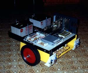
- The onboard computer
I used an old 386DX40 small sized computer for the "brains"
of the robot lawnmower. It's maybe a bit of an overkill but it
was simply available and I enjoy controlling the outside world
via the printer port. It is a cheap and easy method for computer
control. As can be seen above , I cut the motherboard mounting
area from an old desktop computer case for use as supporting
hardware for the video / printer port card , the floppy disk
controller card and also the 386 motherboard.
The new 21 Mac 2013 Model II
Notes:
Robot Lawnmower

The 386 PC Controller has now been removed and will be
replaced by a PIC16F84 Micro controller which solves the
problem of having to boot from the floppy drive and also solves
the power supply problem. Programming the PIC is not as
straightforward as programming the 386 PC's printer port
though as it has to be done using PIC assembler. (I use the
MPLAB assembler from Microchip)
Here is an example program to send a signal to one of the
robot's motors via the motor relay driver board.
(5 Seconds ON / 5 Seconds OFF) IOControl.ASM
robot's motors via the motor relay driver board.
(5 Seconds ON / 5 Seconds OFF) IOControl.ASM
See the table for wiring instructions to the PIC Micro controller 
- The onboard power supply
I used second hand YUASA Gel batteries which were replaced
by new ones in computer UPS systems. Two 6 volt batteries are
wired in parallel to supply sufficient power to the 386 PC via a
silicon diode bridge to drop the voltage down to approximately
5 volts required by the PC. No fancy voltage regulation at this
stage but it must get the highest priority for the future.
The third battery is a 12 volt battery used for the wiper motors ,
cutter motor and automotive switching relays shown below.
I may even add a second 12 volt battery to power the cutter
motor alone seeing this motor can draw currents in excess of
5 amps and over 20 amps on startup!
Notes:
21 Mac 2013
A 7805 voltage regulator is used to drop the 12 volt supply
down to 5 volts to provide power to the PIC Micro controller.
An important point is the use of 33 microfarad tantalum
capacitors on the input and output of the regulator and a
100 nanofarad capacitor across the supply terminals of the
PIC IC to prevent noise affecting the PIC Micro controller
due to the switching of the wiper motors.
The whole setup is not as efficient as one would like it to be ,
but this was to get something going with no unnecessary
problems to get it done. No electronic H Bridges and speed
control circuitry although I have plans to use an output of the
printer port for a software controlled pulse width modulated
signal for possible speed control when applying power to the
wiper motors and possibly even the cutter motor too.
The cutter itself will probably be in the form of a bush cutter's
blade or edge trimmer. This still has to be experimented with.

- The I/O system
All I/O control is done via the printer port (LPT1) of the
onboard 386 PC. The outputs from the infrared detector kits
are fed from the open collector transistor output to the input
interface module. Further inputs will be read from various
other sensors via the input interface module when the budget
allows it.
onboard 386 PC. The outputs from the infrared detector kits
are fed from the open collector transistor output to the input
interface module. Further inputs will be read from various
other sensors via the input interface module when the budget
allows it.
Notes:
21 Mac 2013
See above , concerning the new PIC16F84 Micro controller.
The input interface module is basically just a biasing network
for the input lines on the printer port. The lines are biased
to +5 volts via 1 to 10K resistors and can also provide a supply
to the open collector sensor output circuitry.
for the input lines on the printer port. The lines are biased
to +5 volts via 1 to 10K resistors and can also provide a supply
to the open collector sensor output circuitry.
Notes:
21 Mac 2013
See above , concerning the new PIC16F84 Micro controller.

- The manual computer command simulator
When the PC is not running , I have a computer command
simulator to switch the motors on , off , forward and reverse
to give desired robot movements. This is simply a box of switches
interfaced to the output control circuitry.
simulator to switch the motors on , off , forward and reverse
to give desired robot movements. This is simply a box of switches
interfaced to the output control circuitry.
- Software development
Originally , the software was written using Visual Basic for
DOS which I found on the internet and although it is slow ,
it allows me to do event driven programming which is a little
better than using languages like PASCAL or normal BASIC.
I just have to plug in a standard IBM PC Keyboard and Mono
screen. I use a removable 1.44 Mb floppy drive to boot the PC
with DOS and load the program into memory. Thereafter
I remove the floppy drive and the program continues normally
running in the 2 Mb of onboard RAM.
Notes:
21 Mac 2013
See above , concerning the new PIC16F84 Micro controller.
A program I wrote in PIC16F84 assembler to simulate all the
Mach 2001 Model II robot movements can be viewed here.
A program I wrote in PIC16F84 assembler to simulate all the
Mach 2001 Model II robot movements can be viewed here.
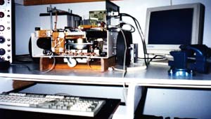
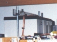
The MACH 2013 Robot Lawnmower being programmed
I have built a wooden stand as can be seen above under the
robot to prevent traction of the wheels while simulating
behaviors in response tosensor input (Stimulus). Almost sounds
like psychology but is it at all anything else? The infrared
detector units are not shown in this picture , but have they been
mounted on both sides in the front , with adjustable brackets to
be able to get the correct angle to be effective in detecting
objects from the front and sides of the robot.
- The cost of building the MACH 2013 Robot Lawnmower
I thought it would be of interest to mention what my robot lawnmower
cost to make it a reality and it is by no means complete.
cost to make it a reality and it is by no means complete.
| Chassis (Cover from an old electronics unit) Free |
| Second hand Gel batteries Free |
| Angle iron for mounting brackets Free |
386DX40 Motherboard + 2Mb RAM (No longer used) Free
|
| Video / LPT card and IDE controller card Free |
| PIC16F84 and programmer unit Donated |
| DC Trip switches for the 12 an 5 volt supplies Free |
| Additional hardware (Bolts and nuts) R 30-00 |
1.44 Mb Floppy drive (No longer used) Reusable
|
| Two second hand wiper motors R 300-00 |
| One second hand fan motor R 100-00 |
| Lawnmower wheels R 140-00 |
| Castors (Had to buy 4 of) R 60-00 |
| Automotive relays R 100-00 |
| Electronic components and Vero board R 100-00 |
| Two Infrared TX/RX kits R 111-00 |
| TOTAL R 941-00 |
To compare internationally , South Africa's Rand is equivalent
to approximately R 8-30 to the dollar and to date
(25 October 2001) R 9-30.
to approximately R 8-30 to the dollar and to date
(25 October 2001) R 9-30.
- Contact information
Email is most welcome.
I would love to share ideas with other robotics enthusiasts.
I know my robot is very primitive and still needs a lot of
attention. The important thing to do in the near future is to
replace the two balancing castors with a large third castor to
assist with movement over grass. The small ones tend to get in
the way.
I know my robot is very primitive and still needs a lot of
attention. The important thing to do in the near future is to
replace the two balancing castors with a large third castor to
assist with movement over grass. The small ones tend to get in
the way.
I can be contacted at the following email address:
edleighton@hotmail.com .
edleighton@hotmail.com .


Tiada ulasan:
Catat Ulasan