Photovoltaic Power System and Wiring Module Interconnection

Photovoltaic (PV) is the field of technology and research related to the application of solar cells for energy by converting sunlight directly into electricity. The following Photovoltaic Power System manual is a suggested practices manual examines the requirements of the 2005 National Electrical Code (NEC) as they apply to photovoltaic (PV) power systems. In this manual you will get the design requirements for the balance-of-systems components in a PV system are addressed, including conductor selection and sizing, overcurrent protection device rating and location, and disconnect rating and location.This manual is divided into sections which covers discussion on Photovoltaic Modules (including Modules Marking, Wiring, Module Interconnection, Tracking Modules, Terminals, Transition Wiring, Module Connection Access, Module Connectors, and Splices), Conductor Color Code, PV Array Ground-Fault Protection, PV Array Installation and Service, Grounding (including size of DC grounding electrode conductor, point of connection, charge controller, ungrounded system), Equipment Grounding, Inverter AC Outputs, Conductor Ampacity, Overcurrent Protection, Batteries, Generators, Charge Controller, Inverters, Stand Alone Distribution System, etc.
Copper conductors are recommended for almost all photovoltaic system wiring. Copper conductors have lower voltage drops and better resistance to corrosion than other types of comparably sized conductor materials. Aluminum or copper-clad aluminum wires can be used in certain applications, but the use of such cables is not recommended—particularly in dwellings. All wire sizes presented in this guide refer to copper conductors.
Find more information about Photovoltaic Power System and Wiring Module Interconnection in the following manual. (source: scribd.com)
Photovoltaic Transimpedance Amplifier Circuit Diagram

The following schematic shows thePhotovoltaic Transimpedance Amplifier Circuit Diagram. This design combines two Intersil X9258T digitally controlled potentiometers with an AD822 low noise dual op amp to create a flexible, digitally calibrated, wide dynamic range transimpedance amplifier topology that can be used with virtually any photovoltaic detector technology. The amplifier output is given by:Vo = Is(1MΩ) ((1+P1)/(256-P1))
Where P1 is the 8-bit (0 to 255) digital value written to DCP1. For more detail information on Photovoltaic Transimpedance Amplifier Circuit Diagram, download the following file.
EPSON Stylus PHOTO RX600|610 RX620|630 Pinout Connector Diagram
The following table provides detail of EPSON Stylus PHOTO RX600|610 and RX620|630 pinout andconnector.
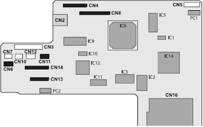

| CN No. CN3 CN4 CN5 CN6 CN7 CN8 CN10 CN11 CN12 CN13 CN14 | Color White (FFC) White Red White (FFC) White Black White (FFC) (FFC) | Pins 14 25 5 4 3 30 3 4 4 19 25 | Connection Point Power Unit CCD Module TPU Inlet Holder Scanner Motor HP sensor circuit board Panel circuit board Detector circuit board CR Motor PF Motor Print Head Print Head |
Home Wiring Installation, Testing and Troubleshooting – a Complete Guide eBook
The following ebook you will find, provides a comprehensive manual for home wiring system from basic repairs to advanced projects.

This ebook manual is divided into sections covering topics onPlanning a Wiring Project, Circuit Maps for Common Wiring Layout,Wiring Installation Basic (covers discussion on tools, materials and technique, electrical boxes for projects, installing electrical boxes, wires and cables for projects, installing NM cable, Conduit, Circuit Breaker Panels, Connecting Circuit Breakers, installing outdoor wiring, mounting the distribution centers, routing cables and wires, installing an audio system, making final connections, testing the system and troubleshooting problems etc. Here is a quotation from the ebook:
An electrical circuits is a continuous loop. Household circuits carry power from the main service panel, throughout the house, and back to the main service panel. Several switches, receptacles, light fixtures, or appliances may be connected to a single circuit. Current enters a circuit loop on hot wires and returns along neutral wires. These wires are color coded for easy identification. Hot wires are black or red, and neutral wire are white or light gray.
Find more information about Home Wiring Installation, Testing and Troubleshooting - a Complete Guide eBook in the following Complete Guide to Home Wiring Diagram .
.
An electrical circuits is a continuous loop. Household circuits carry power from the main service panel, throughout the house, and back to the main service panel. Several switches, receptacles, light fixtures, or appliances may be connected to a single circuit. Current enters a circuit loop on hot wires and returns along neutral wires. These wires are color coded for easy identification. Hot wires are black or red, and neutral wire are white or light gray.
.


Tiada ulasan:
Catat Ulasan